| Structures over the HSR line Madrid - Extremadura | |
| Navalmoral de la Mata, Spain | |
| Structural typology | Railway Bridges |
| Date | February, 2014 |
| Scope | Detailed design and construction support |
| Cliente | OHL |
| Design | Fhecor |
| Construction | OHL |
| Owner | ADIF (Administrador de Infraestructuras Ferroviarias) |
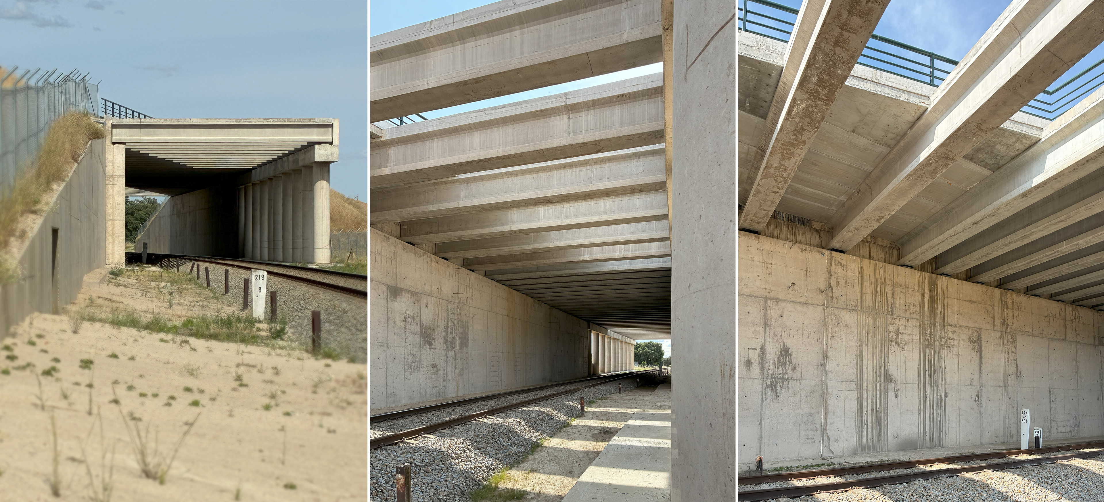
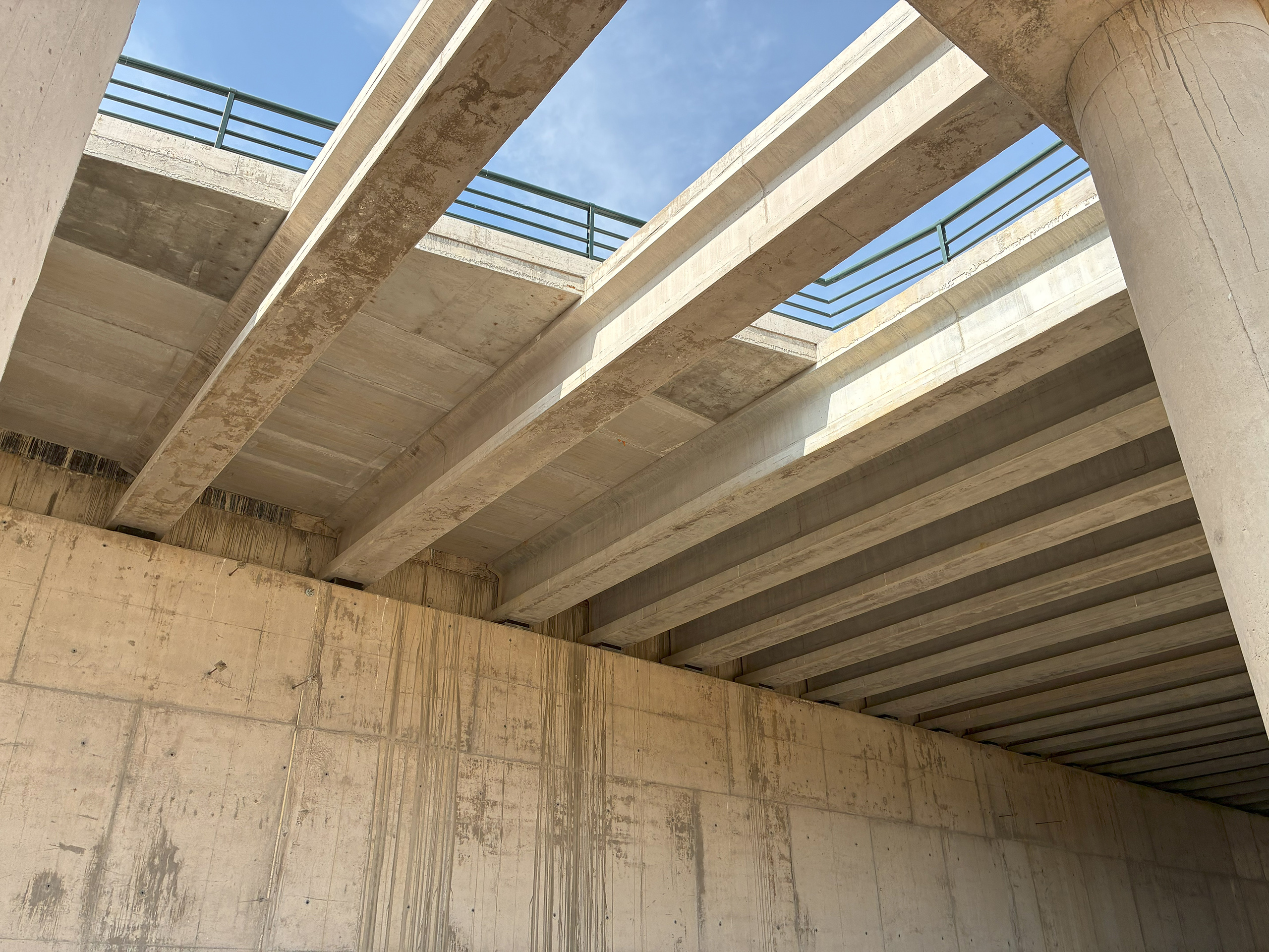
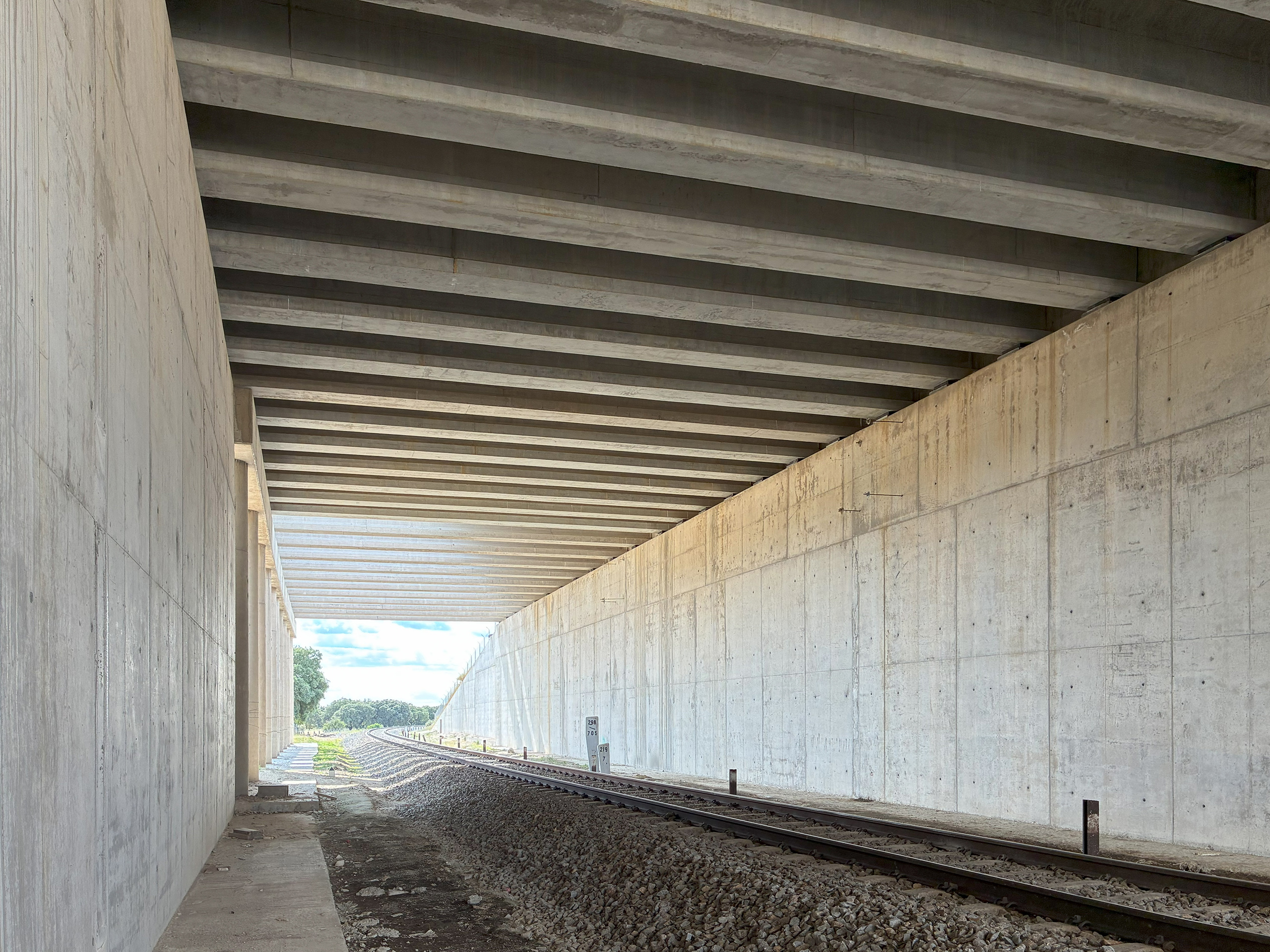
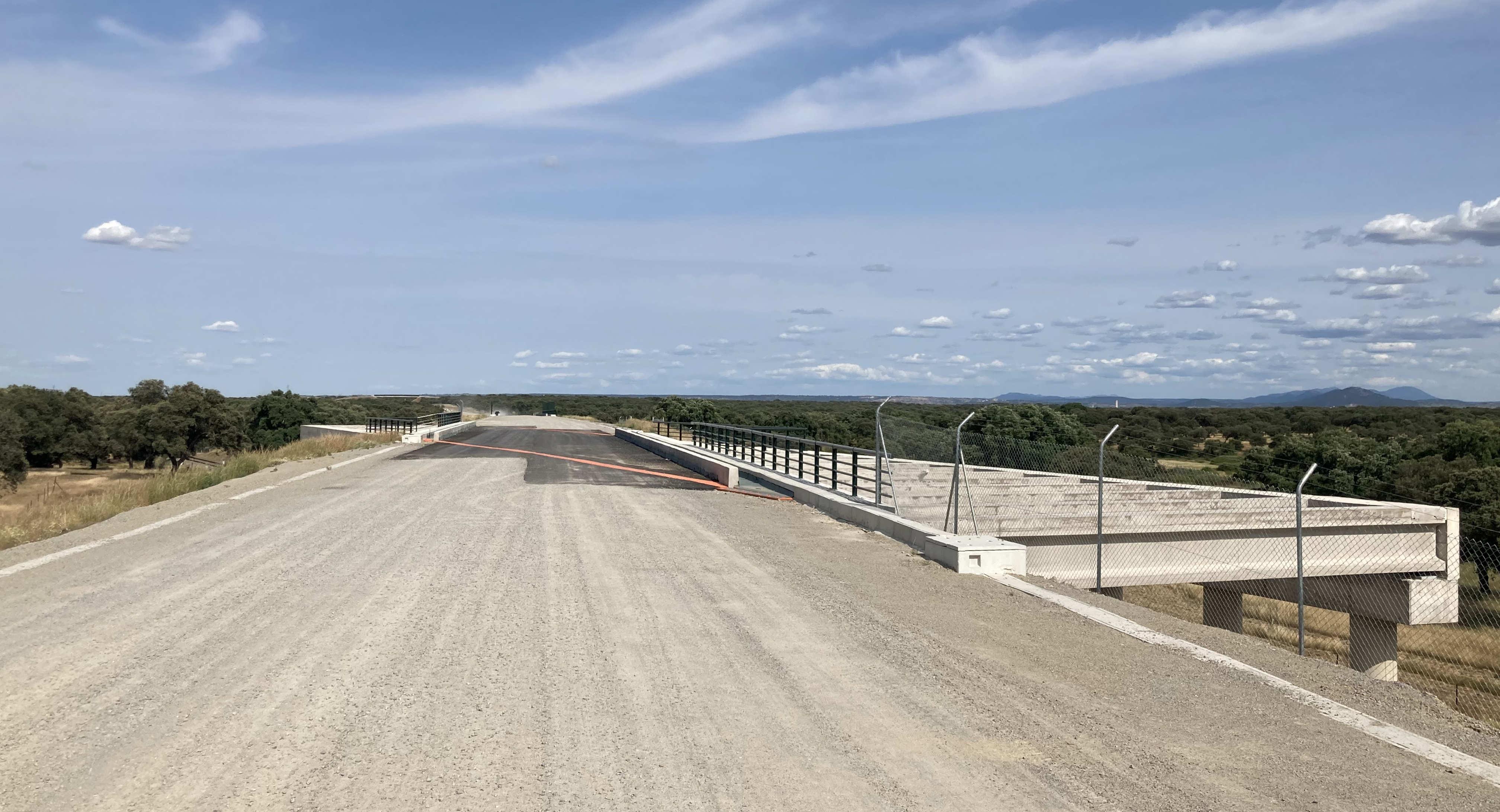
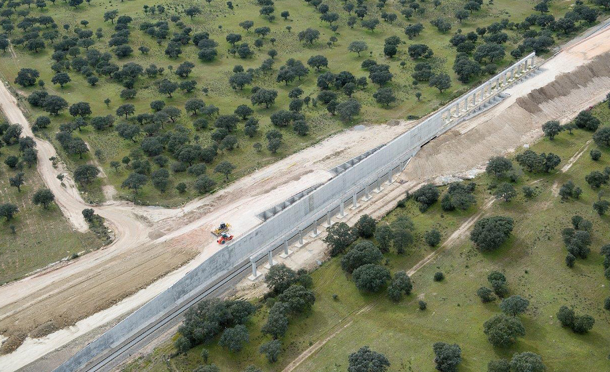
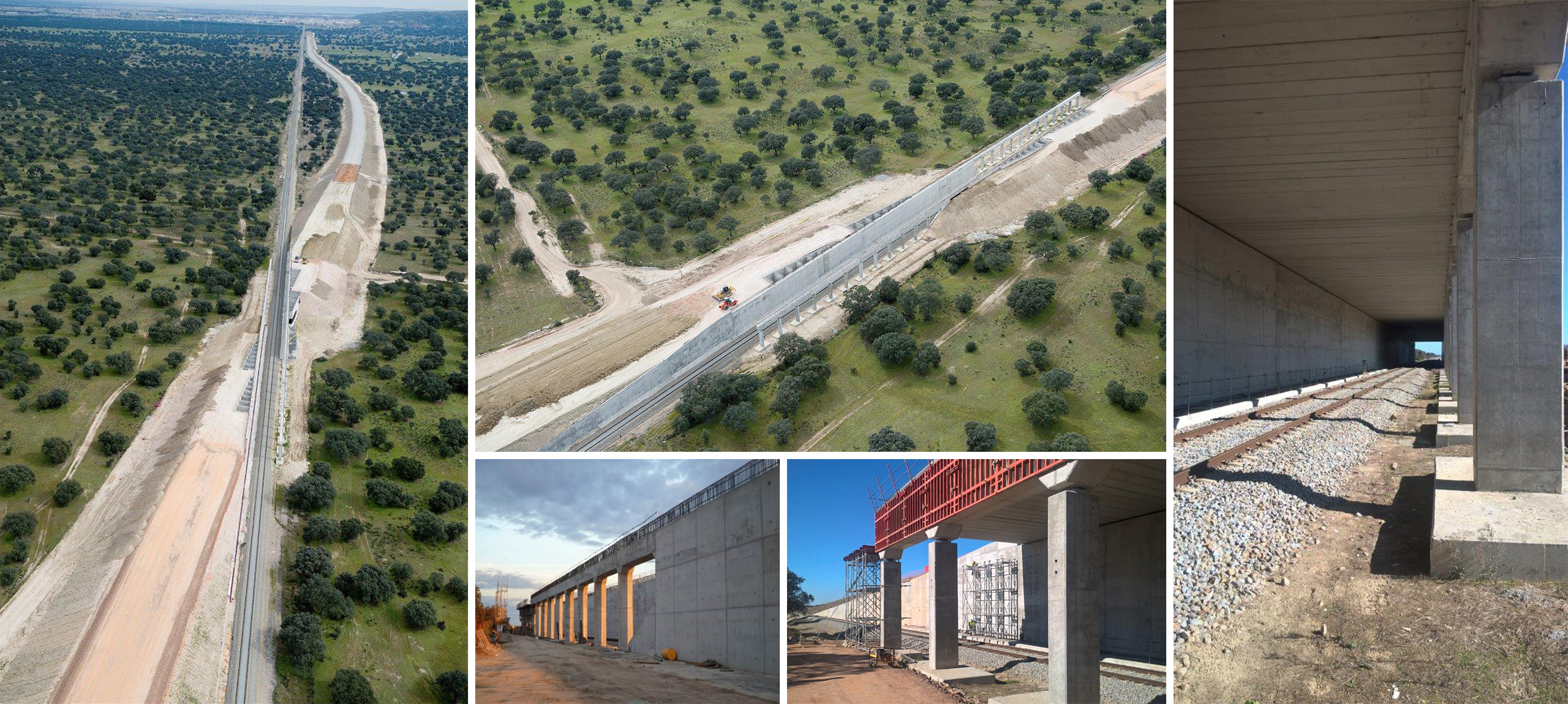
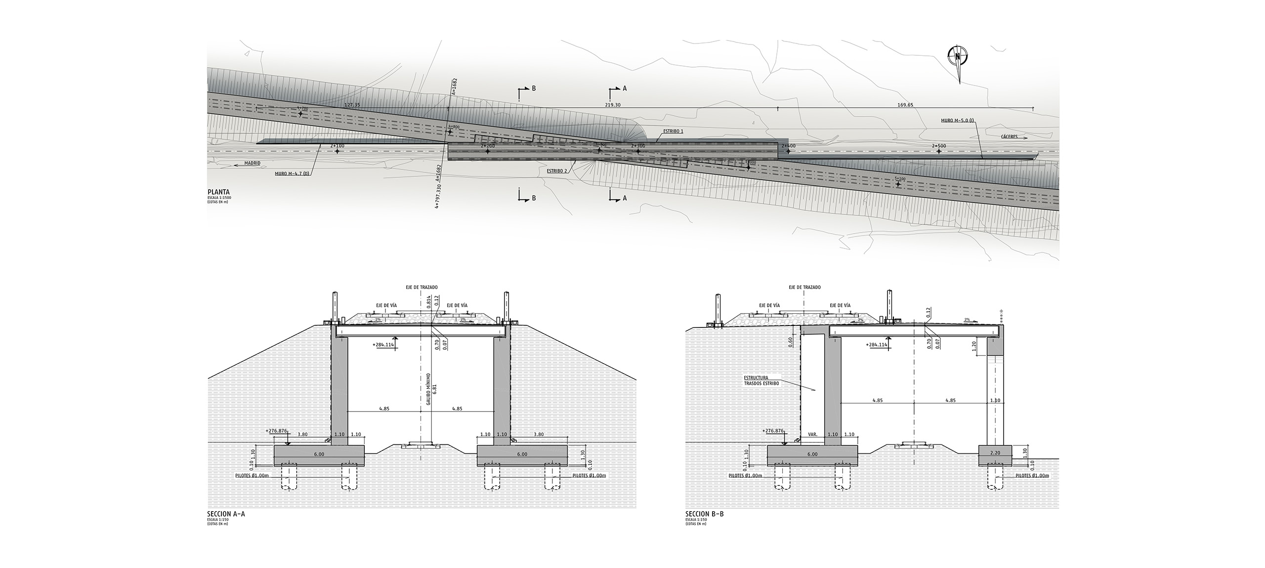
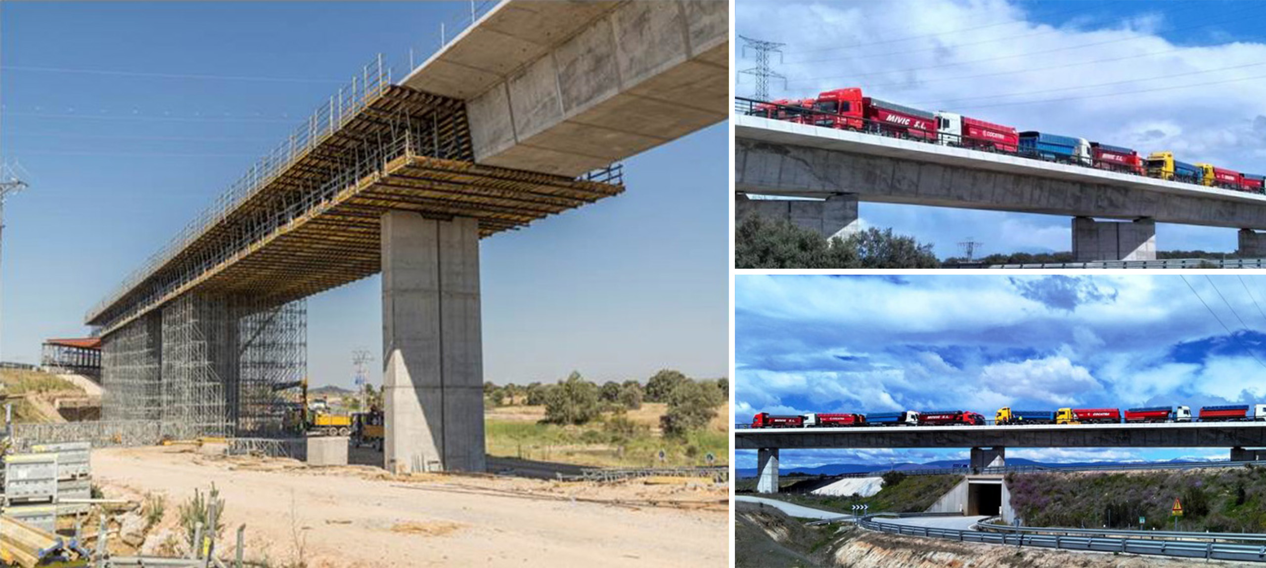
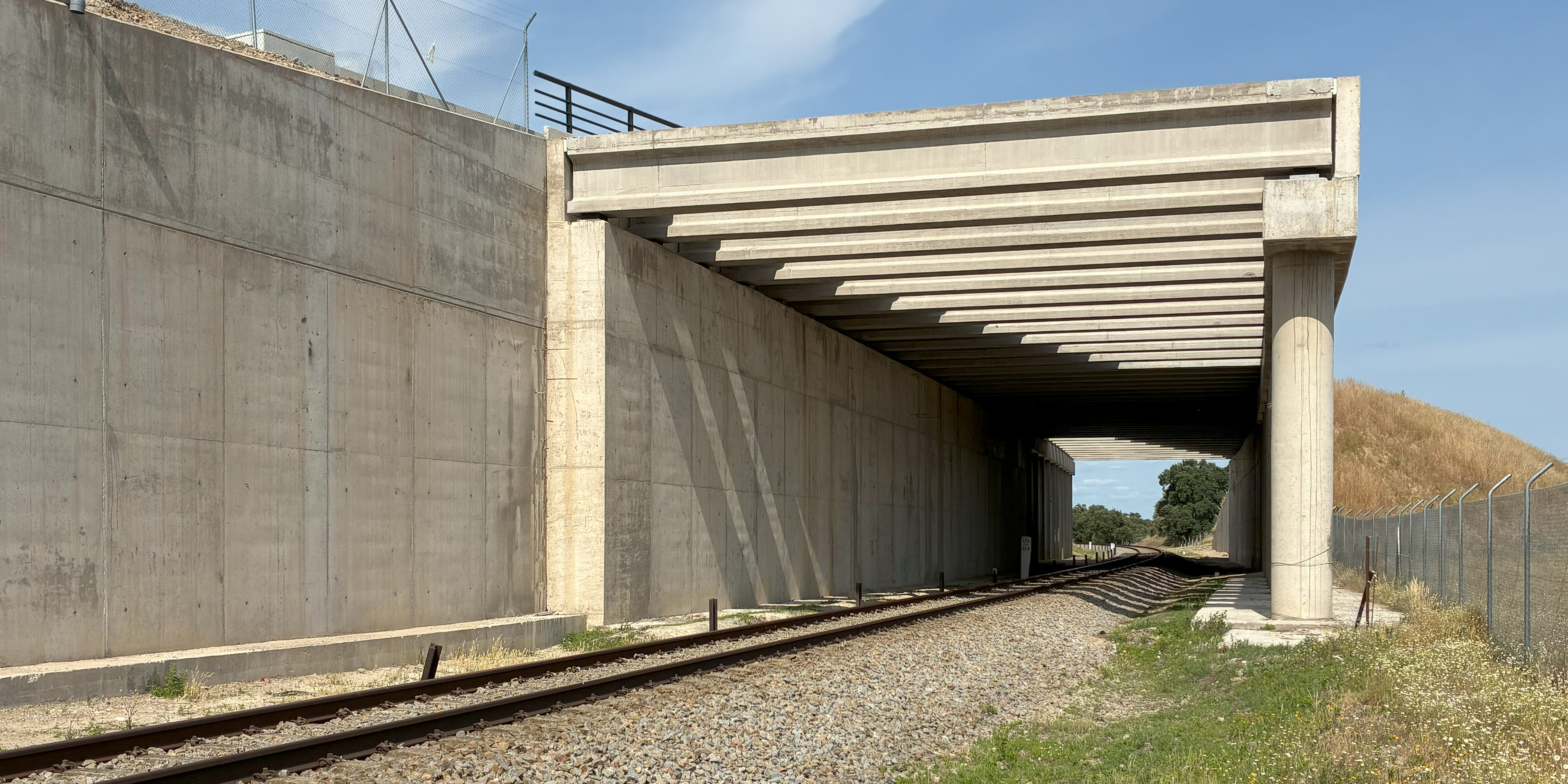
The structure consists of an isostatic pergola with a single span of 10.50 m (design span) over the existing railway, which is crossed obliquely by high-speed train lines at an angle of approximately 7 centesimal degrees. The deck typology is a beam-slab system with prestressed beams measuring 0.70 m in depth, spaced at 0.67 m intervals, and a compression slab with a minimum thickness of 0.07 m, resulting in a total structural depth of 0.77 m.**
The compression slab has a variable thickness, with a minimum depth of 7 cm at the ends and a 2% camber on both sides of the high-speed line axis, reaching a maximum depth of 19 cm at the center.
The deck is subdivided into two zones: Zone 1, the central area under the railway tracks, which is 105 m long; and Zone 2, the exterior areas of the deck. The number of prestressing tendons in the beams varies between these two zones, with 8 strands of 0.6” diameter in Zone 1 and 6 strands of 0.6” diameter in Zone 2.
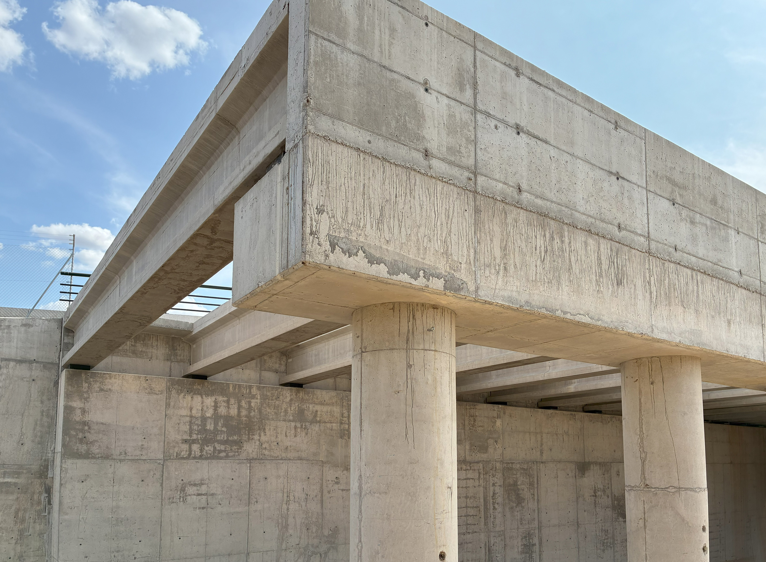
Due to the structure’s typology, elastomeric bearings with confinement reinforcement are placed under the beams. Two bearing sizes have been defined according to the maximum loads they must support: 150x200 mm bearings on the abutment walls, and 100x150 mm bearings in the pier zone. The total height of the bearings is 28 mm, with a net height of 20 mm in both cases.
The compression slab has a variable thickness, with a minimum depth of 7 cm at the ends and a 2% camber on both sides of the high-speed line axis, reaching a maximum depth of 19 cm at the center.
The deck is subdivided into two zones: Zone 1, the central area under the railway tracks, which is 105 m long; and Zone 2, the exterior areas of the deck. The number of prestressing tendons in the beams varies between these two zones, with 8 strands of 0.6” diameter in Zone 1 and 6 strands of 0.6” diameter in Zone 2.
Due to the structure’s typology, elastomeric bearings with confinement reinforcement are placed under the beams. Two bearing sizes have been defined according to the maximum loads they must support: 150x200 mm bearings on the abutment walls, and 100x150 mm bearings in the pier zone. The total height of the bearings is 28 mm, with a net height of 20 mm in both cases.