dsc06486_fly_7356.jpg
Centura Bridge
Circunvalación Norte de Bucarest, Rumania
Structural typology Cable Stay Bridges
Date December, 2010
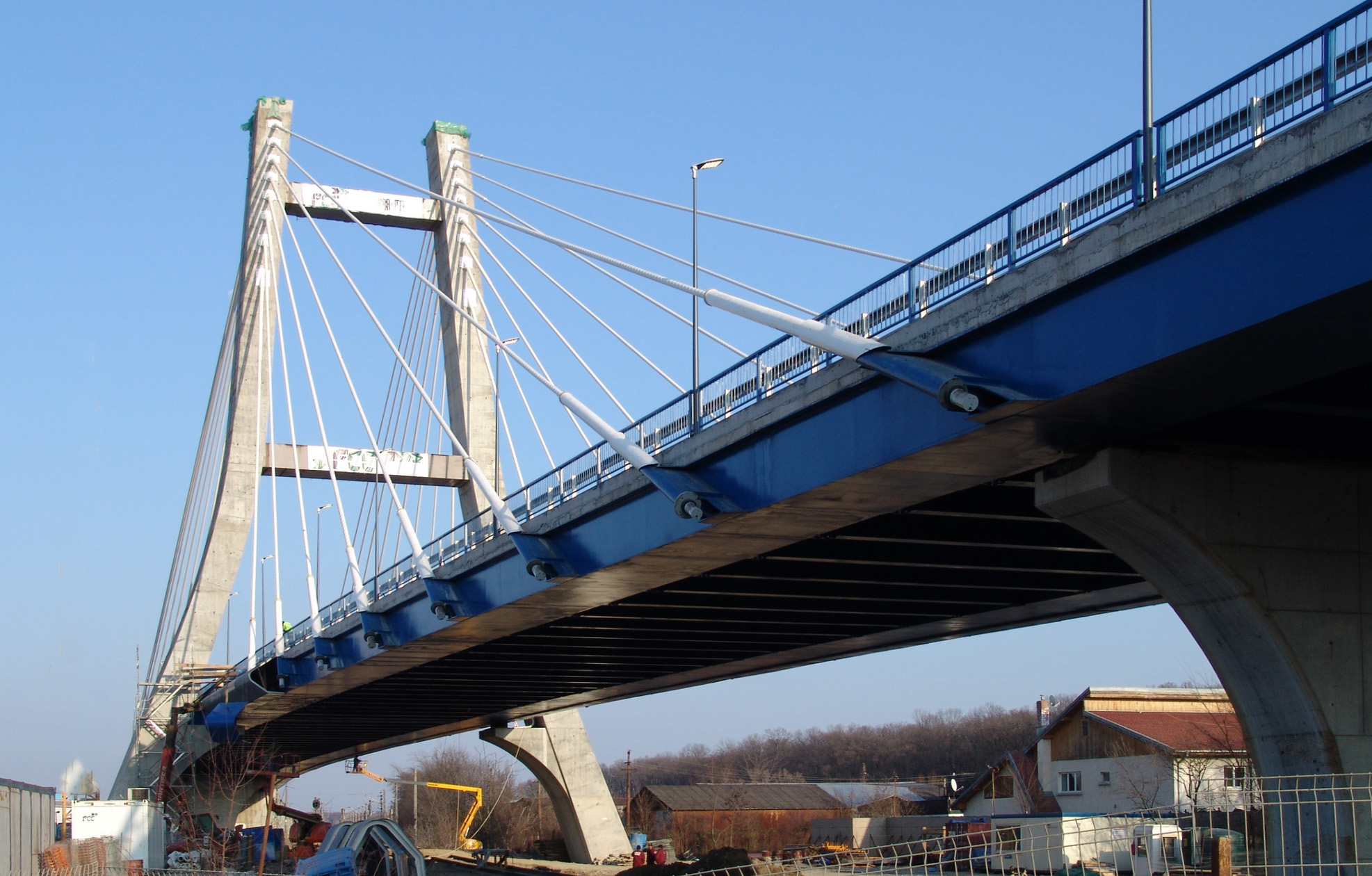
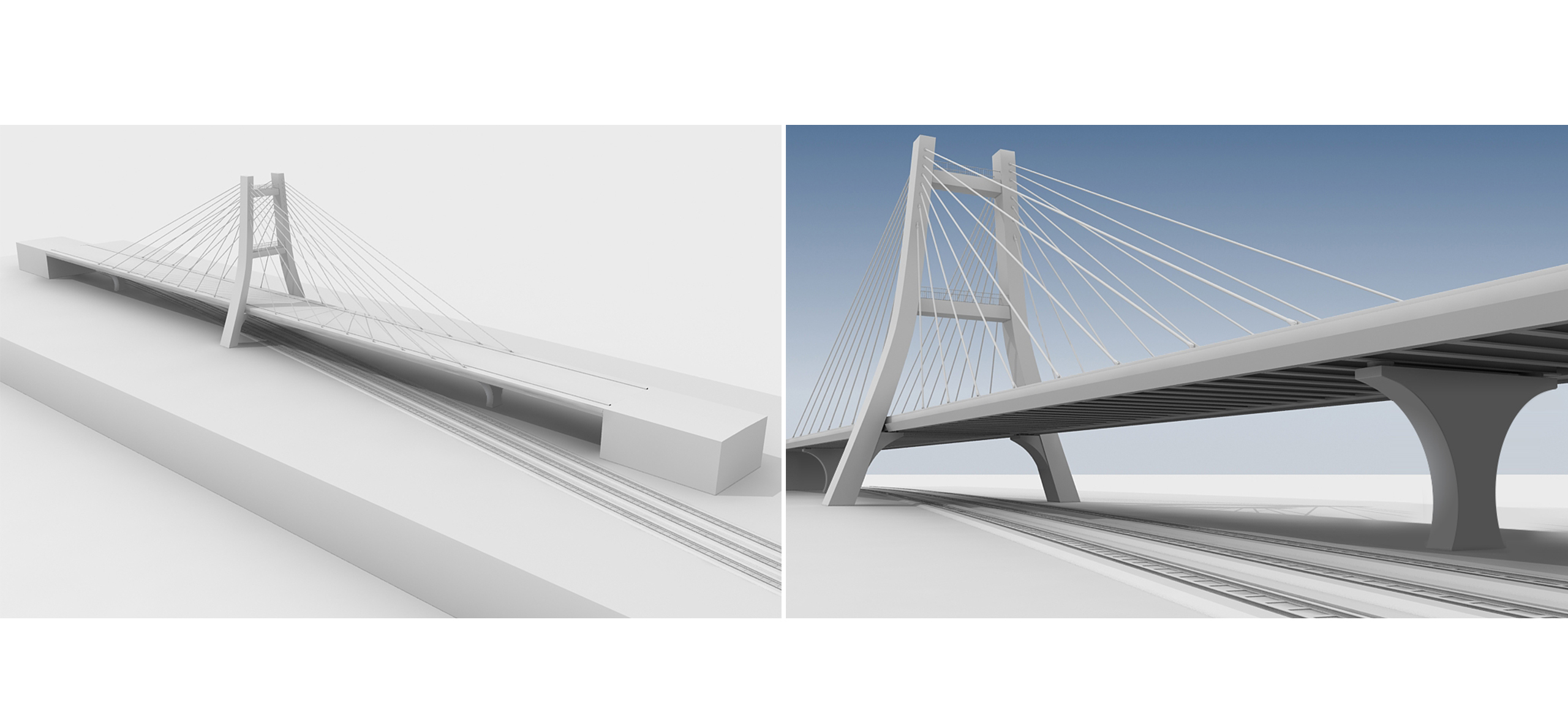
The "Centura Bridge" has a 35+85+85+35m span distribution, with a central pylon and two intermediate piers. The need of these piers rises from the impossibility of building a taller pylon due to height restrictions imposed by the proximity of a nearby airport.

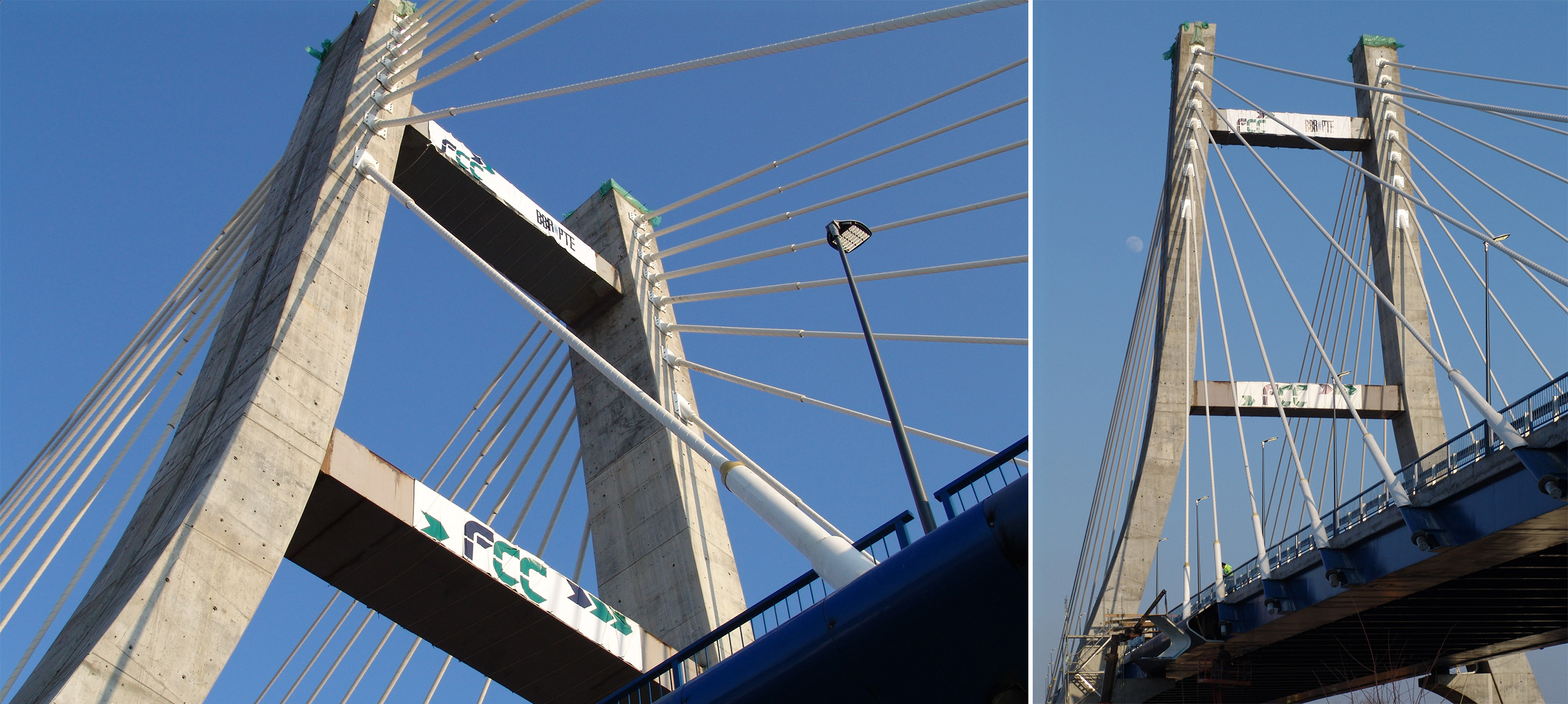
Thus, with a 47m high pylon (37m above deck) the positioning of these intermediate piers is imposed by the maximum permissible slope of the cables whilst still maintaining effectiveness.

The 20.30 wide deck is composed of two steel box girders 2.50m wide at the bottom, with upper flanges of 0.50m, so giving a total beam width of 3.0m. The box girders are pin-jointed together with cross-joisting. A 2mm thick corrugated steel sheeting is placed upon the box girder and transversal beam framework which receives a 0.25m thick slab cast in-situ.

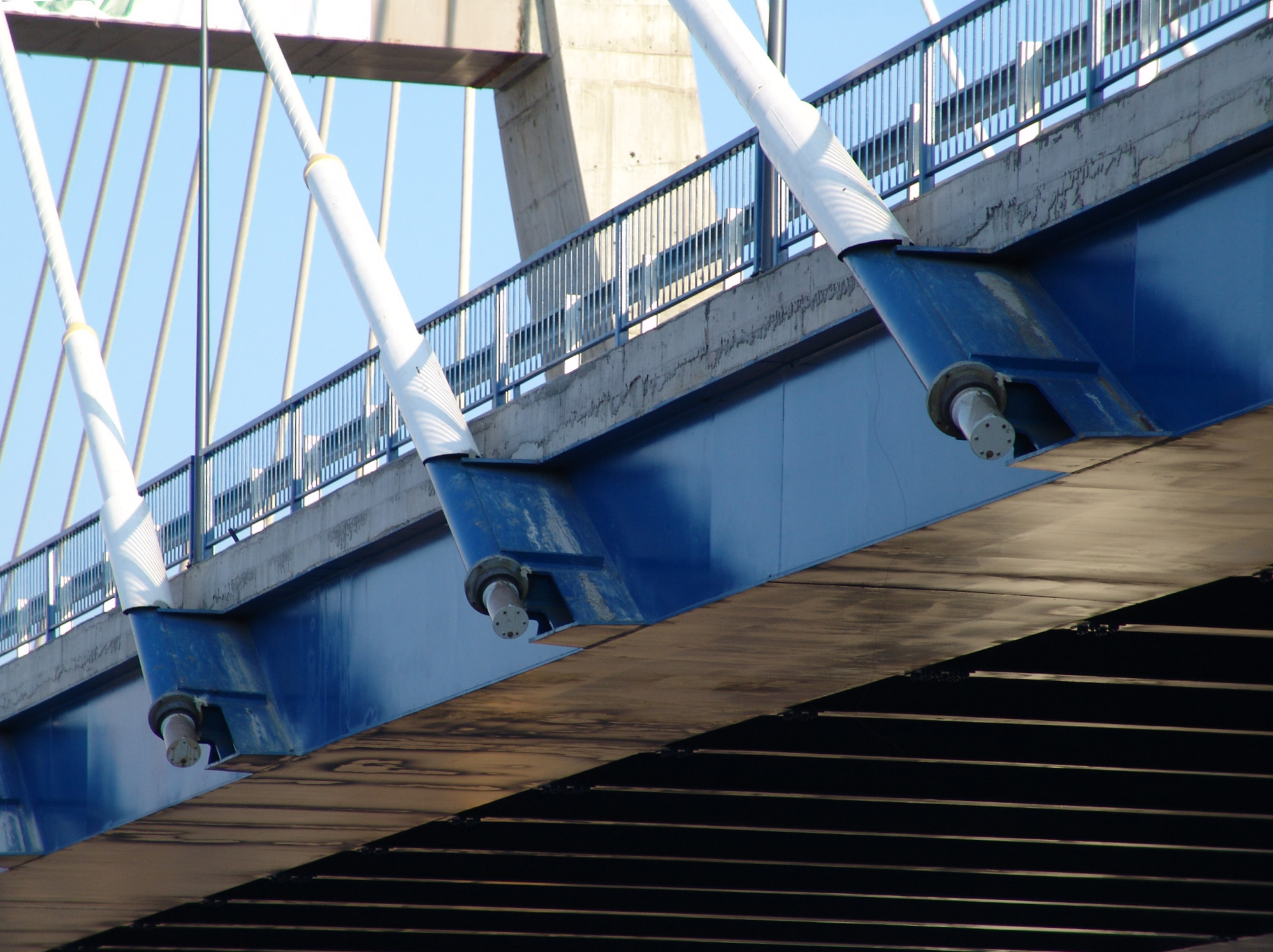
The cables are composed of between 78 and 133 seven millimeter wires which are anchored to the deck via special welded steel plates.
Pro
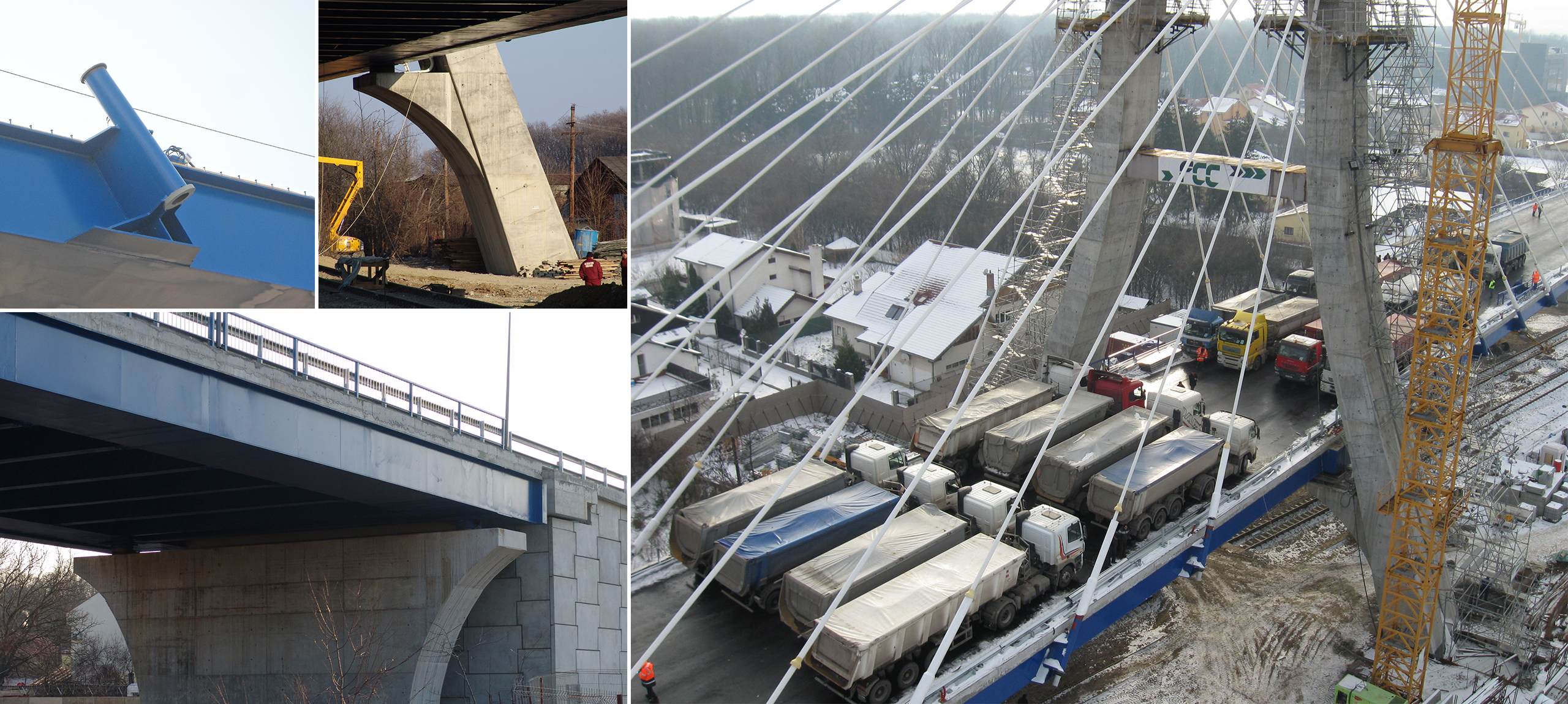
The elevations are curve-shaped. In the case of the pylon, such a curvature tries to maintain the aspect of the original project and at the same time includes the pylon leg in the cable plane. This pylon is hollow from the deck up. The curvature in abutments and piers comes from the need to adapt their shape to the railway track clearance height. At the abutments, basic functions are separated; the concrete wall withstands the loads coming from the deck, and a reinforced soil wall hold the ground under the road.
It is worthy of highlighting the connection between the deck and elevations, with lead rubber bearings in the pylon and abutments and free spherical pot bearings in the piers. These LRB are specially indicated to dissipate energy by means of a hysteretic cycle.
The "Centura Bridge" has a 35+85+85+35m span distribution, with a central pylon and two intermediate piers. The need of these piers rises from the impossibility of building a taller pylon due to height restrictions imposed by the proximity of a nearby airport.

Thus, with a 47m high pylon (37m above deck) the positioning of these intermediate piers is imposed by the maximum permissible slope of the cables whilst still maintaining effectiveness.

The 20.30 wide deck is composed of two steel box girders 2.50m wide at the bottom, with upper flanges of 0.50m, so giving a total beam width of 3.0m. The box girders are pin-jointed together with cross-joisting. A 2mm thick corrugated steel sheeting is placed upon the box girder and transversal beam framework which receives a 0.25m thick slab cast in-situ.

The cables are composed of between 78 and 133 seven millimeter wires which are anchored to the deck via special welded steel plates.
The elevations are curve-shaped. In the case of the pylon, such a curvature tries to maintain the aspect of the original project and at the same time includes the pylon leg in the cable plane. This pylon is hollow from the deck up. The curvature in abutments and piers comes from the need to adapt their shape to the railway track clearance height. At the abutments, basic functions are separated; the concrete wall withstands the loads coming from the deck, and a reinforced soil wall hold the ground under the road.

It is worthy of highlighting the connection between the deck and elevations, with lead rubber bearings in the pylon and abutments and free spherical pot bearings in the piers. These LRB are specially indicated to dissipate energy by means of a hysteretic cycle.
Centura Bridge
Circunvalación Norte de Bucarest, Rumania
Structural typology Cable Stay Bridges
Date December, 2010
Scope Detailed design and construction engineering
The "Centura Bridge" has a 35+85+85+35m span distribution, with a central pylon and two intermediate piers. The need of these piers rises from the impossibility of building a taller pylon due to height restrictions imposed by the proximity of a nearby airport.

Thus, with a 47m high pylon (37m above deck) the positioning of these intermediate piers is imposed by the maximum permissible slope of the cables whilst still maintaining effectiveness.

The 20.30 wide deck is composed of two steel box girders 2.50m wide at the bottom, with upper flanges of 0.50m, so giving a total beam width of 3.0m. The box girders are pin-jointed together with cross-joisting. A 2mm thick corrugated steel sheeting is placed upon the box girder and transversal beam framework which receives a 0.25m thick slab cast in-situ.

The cables are composed of between 78 and 133 seven millimeter wires which are anchored to the deck via special welded steel plates.

The elevations are curve-shaped. In the case of the pylon, such a curvature tries to maintain the aspect of the original project and at the same time includes the pylon leg in the cable plane. This pylon is hollow from the deck up. The curvature in abutments and piers comes from the need to adapt their shape to the railway track clearance height. At the abutments, basic functions are separated; the concrete wall withstands the loads coming from the deck, and a reinforced soil wall hold the ground under the road.

It is worthy of highlighting the connection between the deck and elevations, with lead rubber bearings in the pylon and abutments and free spherical pot bearings in the piers. These LRB are specially indicated to dissipate energy by means of a hysteretic cycle.
dsc06484_fly_7357.jpg
compo1_7358.jpg
compo3_7359.jpg
compo2_7360.jpg
location
Related projects