7__6661.jpg
East-West Link
Melbourne, Australia
Typologie Cable Stay Bridges
Date Février, 2014
Constructeur John Holland, Leighton Contractors and Dragados Joint Venture
FHECOR Ingenieros Consultores carried out the study of alternatives and tender design project of two bridges for the new East-West Link in Melbourne, as requested by John Holland, Leighton Contractors and Dragados Joint Venture. They consist of two urban bridges designed to become iconic landmarks for the city: a cable statyed bridge over the East-West Link and Hoddle St. Interchange, and a tube shaped steel truss over the City Link Highway.

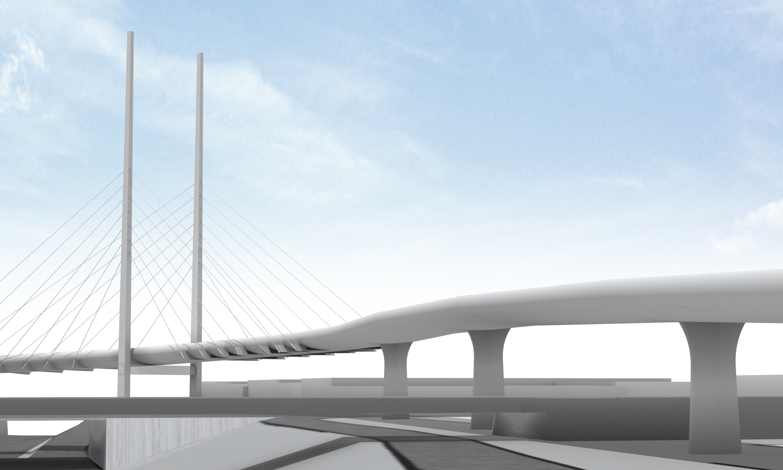
The first structure consists of a viaduct 546 m long with two main spans cable stayed. These two main spans are conditioned by the crossing over the Hoddle St. and the East - West Link, and the curve of R = 90 m of the alignment in plan. The total length is distributed in 2 main spans 88m long, 6 approach spans 50m long and 2 exterior spans 35m long.
The span distribution allows the crossing over some existing bridges (the Hoddle St. and the railway bridge ones) with an adequate vertical clearance, especially over the tracks of the existing railway bridge.
The cross section of the bridge consists of a composite deck of 14 m wide at approach spans and 18 m wide at the two main spans. The structural section is a steel box 1.75 deep and a 25 cm thick concrete slab, and it is cover by a stainless steel architectural cladding all along the bridge. At the external side of the curve in plan a noise barrier has been foreseen.
Pro
The pylon consists of two slender shafts 93 m high whose cross-section is a steel box. The cross section dimension varies between 3.5x3.0 m at the ground level and 1x1 m at the top of the pylon. Both shafts are joined at the deck level by a steel cross beam.
Five PT cable stays are provided at each side from each pylon.

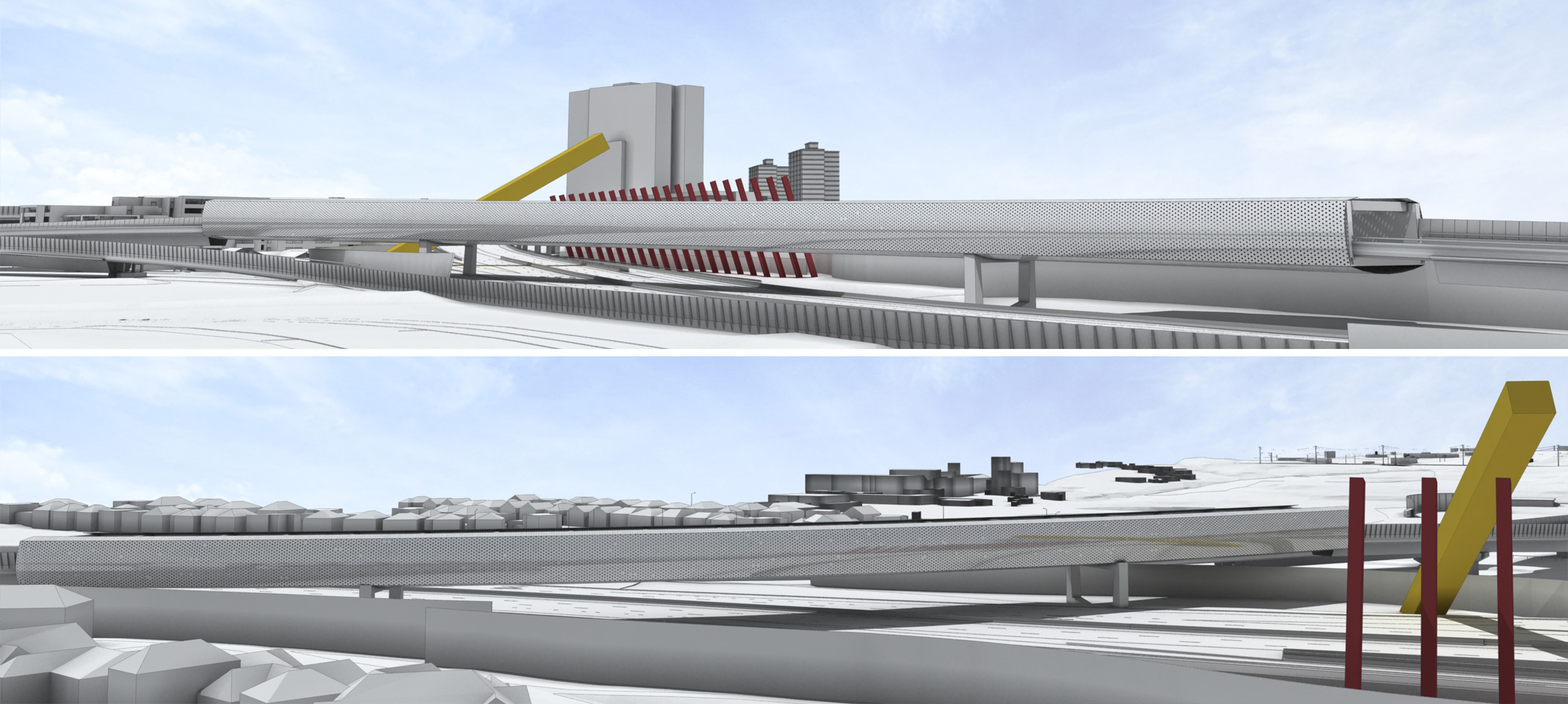
The second structure consists of a viaduct 260 m long with a main span 130 m long and two exterior spans 65m long. The main span is conditioned by the skewed crossing over the City Link Highway, and the curve of approximately R = 335 m of the alignment in plan.
The cross section of the bridge consists of two steel trusses of constant depth, both joined by top and bottom transverse steel beams: bottom beams every 2.4 m and top beams every 15 m. The concrete slab is 15m wide and 25cm thick and it is withstood by the bottom transverse beams.
The whole structural section is covered by a stainless steel cladding at both sides and at the bottom. Thus the visual appearance is a stainless steel tube crossing over the City Link Highway.
The piers consist of two columns, one below each lateral truss girder. The cross section of this column is circular and variable from 1.50 m in diameter at the top.
FHECOR Ingenieros Consultores carried out the study of alternatives and tender design project of two bridges for the new East-West Link in Melbourne, as requested by John Holland, Leighton Contractors and Dragados Joint Venture. They consist of two urban bridges designed to become iconic landmarks for the city: a cable statyed bridge over the East-West Link and Hoddle St. Interchange, and a tube shaped steel truss over the City Link Highway.

The first structure consists of a viaduct 546 m long with two main spans cable stayed. These two main spans are conditioned by the crossing over the Hoddle St. and the East - West Link, and the curve of R = 90 m of the alignment in plan. The total length is distributed in 2 main spans 88m long, 6 approach spans 50m long and 2 exterior spans 35m long.
The span distribution allows the crossing over some existing bridges (the Hoddle St. and the railway bridge ones) with an adequate vertical clearance, especially over the tracks of the existing railway bridge.
The cross section of the bridge consists of a composite deck of 14 m wide at approach spans and 18 m wide at the two main spans. The structural section is a steel box 1.75 deep and a 25 cm thick concrete slab, and it is cover by a stainless steel architectural cladding all along the bridge. At the external side of the curve in plan a noise barrier has been foreseen.
The pylon consists of two slender shafts 93 m high whose cross-section is a steel box. The cross section dimension varies between 3.5x3.0 m at the ground level and 1x1 m at the top of the pylon. Both shafts are joined at the deck level by a steel cross beam.
Five PT cable stays are provided at each side from each pylon.

The second structure consists of a viaduct 260 m long with a main span 130 m long and two exterior spans 65m long. The main span is conditioned by the skewed crossing over the City Link Highway, and the curve of approximately R = 335 m of the alignment in plan.
The cross section of the bridge consists of two steel trusses of constant depth, both joined by top and bottom transverse steel beams: bottom beams every 2.4 m and top beams every 15 m. The concrete slab is 15m wide and 25cm thick and it is withstood by the bottom transverse beams.
The whole structural section is covered by a stainless steel cladding at both sides and at the bottom. Thus the visual appearance is a stainless steel tube crossing over the City Link Highway.
The piers consist of two columns, one below each lateral truss girder. The cross section of this column is circular and variable from 1.50 m in diameter at the top.
East-West Link
Melbourne, Australia
Typologie Cable Stay Bridges
Date Février, 2014
Constructeur John Holland, Leighton Contractors and Dragados Joint Venture
Mission Tender design
FHECOR Ingenieros Consultores carried out the study of alternatives and tender design project of two bridges for the new East-West Link in Melbourne, as requested by John Holland, Leighton Contractors and Dragados Joint Venture. They consist of two urban bridges designed to become iconic landmarks for the city: a cable statyed bridge over the East-West Link and Hoddle St. Interchange, and a tube shaped steel truss over the City Link Highway.

The first structure consists of a viaduct 546 m long with two main spans cable stayed. These two main spans are conditioned by the crossing over the Hoddle St. and the East - West Link, and the curve of R = 90 m of the alignment in plan. The total length is distributed in 2 main spans 88m long, 6 approach spans 50m long and 2 exterior spans 35m long.
The span distribution allows the crossing over some existing bridges (the Hoddle St. and the railway bridge ones) with an adequate vertical clearance, especially over the tracks of the existing railway bridge.
The cross section of the bridge consists of a composite deck of 14 m wide at approach spans and 18 m wide at the two main spans. The structural section is a steel box 1.75 deep and a 25 cm thick concrete slab, and it is cover by a stainless steel architectural cladding all along the bridge. At the external side of the curve in plan a noise barrier has been foreseen.
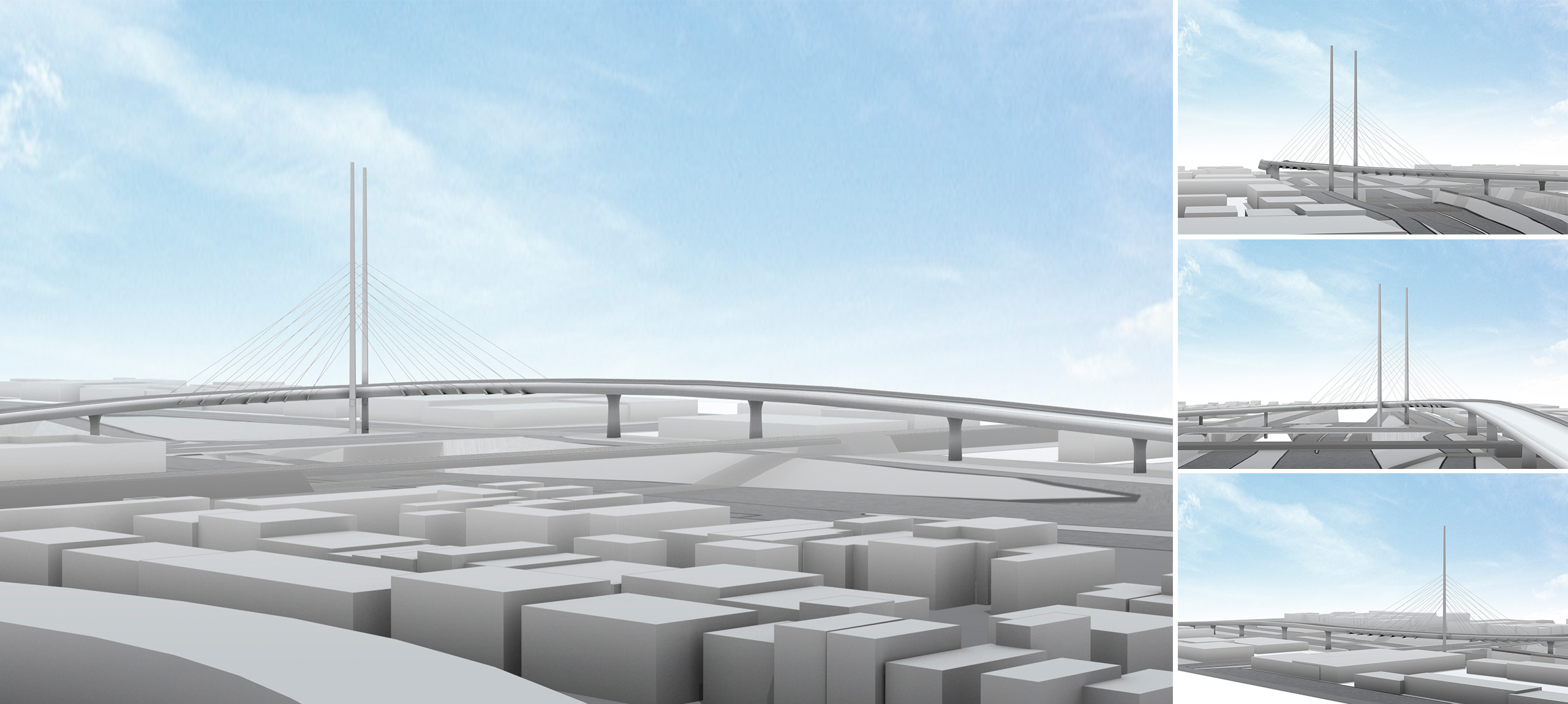
The pylon consists of two slender shafts 93 m high whose cross-section is a steel box. The cross section dimension varies between 3.5x3.0 m at the ground level and 1x1 m at the top of the pylon. Both shafts are joined at the deck level by a steel cross beam.
Five PT cable stays are provided at each side from each pylon.

The second structure consists of a viaduct 260 m long with a main span 130 m long and two exterior spans 65m long. The main span is conditioned by the skewed crossing over the City Link Highway, and the curve of approximately R = 335 m of the alignment in plan.
The cross section of the bridge consists of two steel trusses of constant depth, both joined by top and bottom transverse steel beams: bottom beams every 2.4 m and top beams every 15 m. The concrete slab is 15m wide and 25cm thick and it is withstood by the bottom transverse beams.
The whole structural section is covered by a stainless steel cladding at both sides and at the bottom. Thus the visual appearance is a stainless steel tube crossing over the City Link Highway.
The piers consist of two columns, one below each lateral truss girder. The cross section of this column is circular and variable from 1.50 m in diameter at the top.
compo1_6662.jpg
compo2_6663.jpg
emplacement