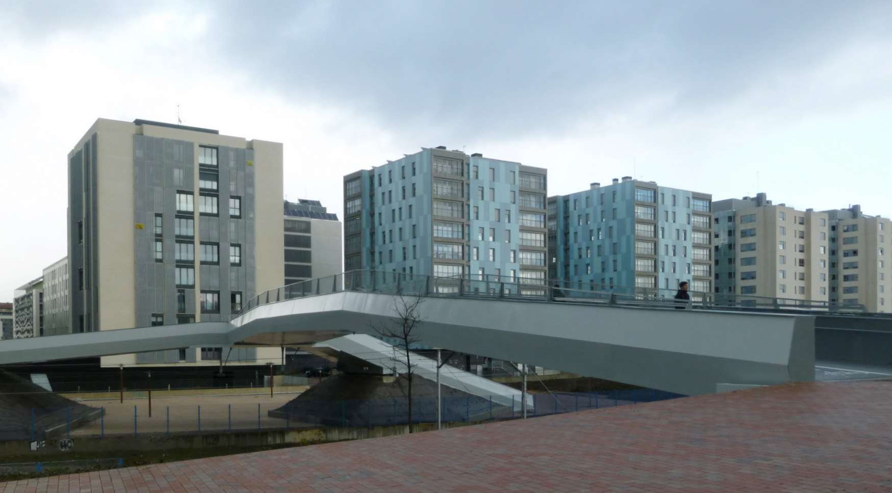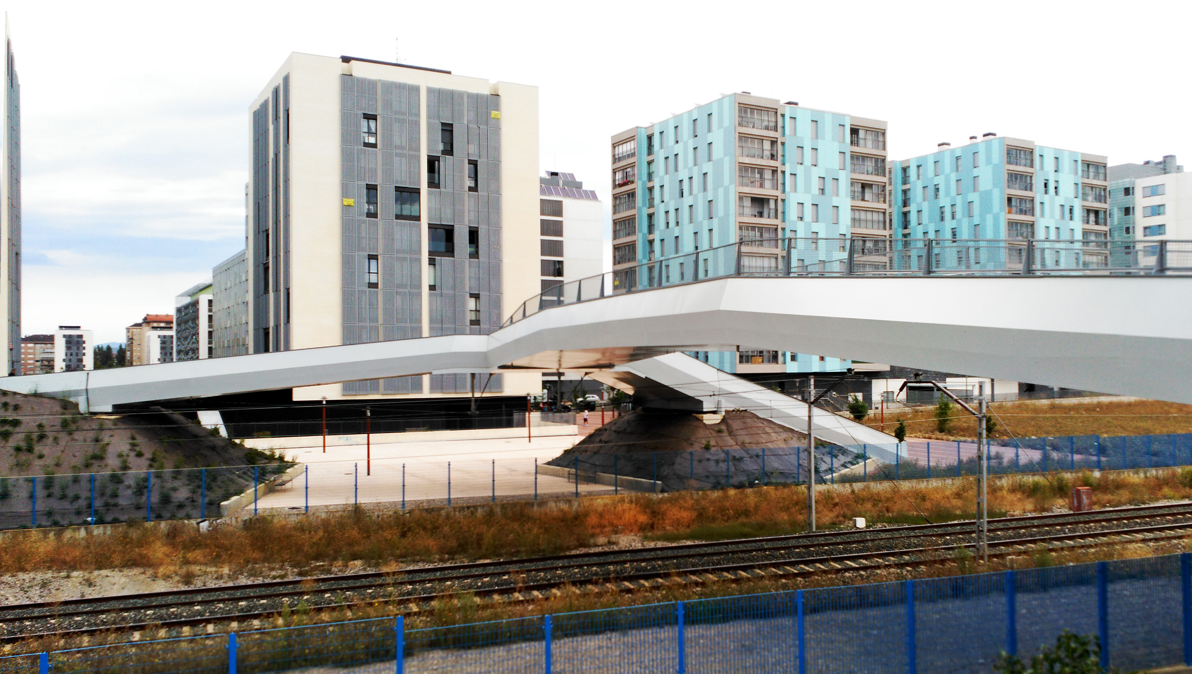
| Zabalgana footbridge over Madrid-Irún railroad | |
| Vitoria Gasteiz, Spain | |
| Structural typology | Pedestrian Bridges |
| Date | September, 2015 |
| Umfang | Detailed design and construction monitoring |
FHECOR won a competition to design the Zabalgana Footbridge in Vitoria, after submitting a proposal based in the following ideas:
A - Functionality
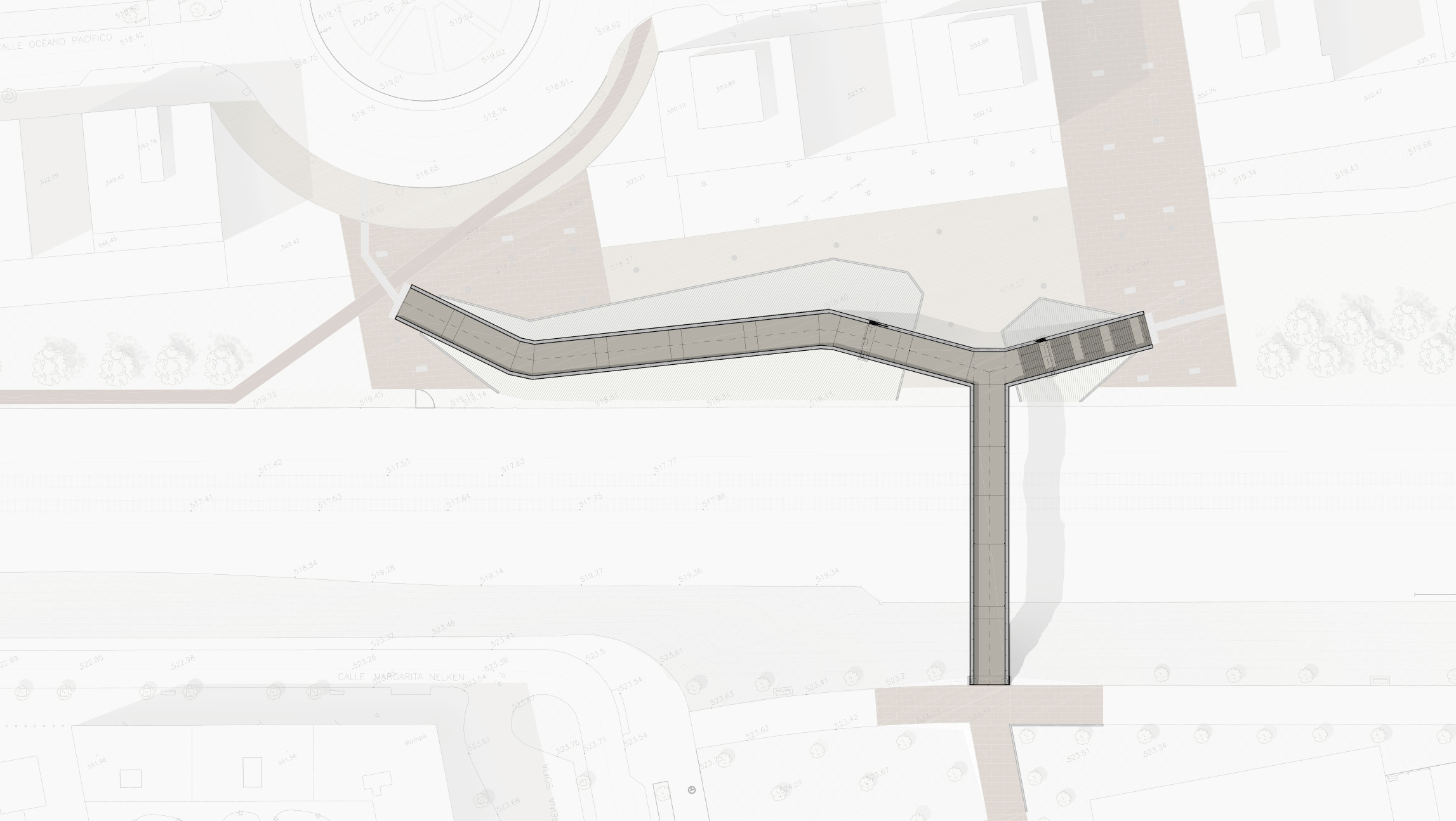
Footbridge location and position allows for minimum pedestrian itinerary, with one southern access close to a school and two northern accesses, where demand is more scattered.
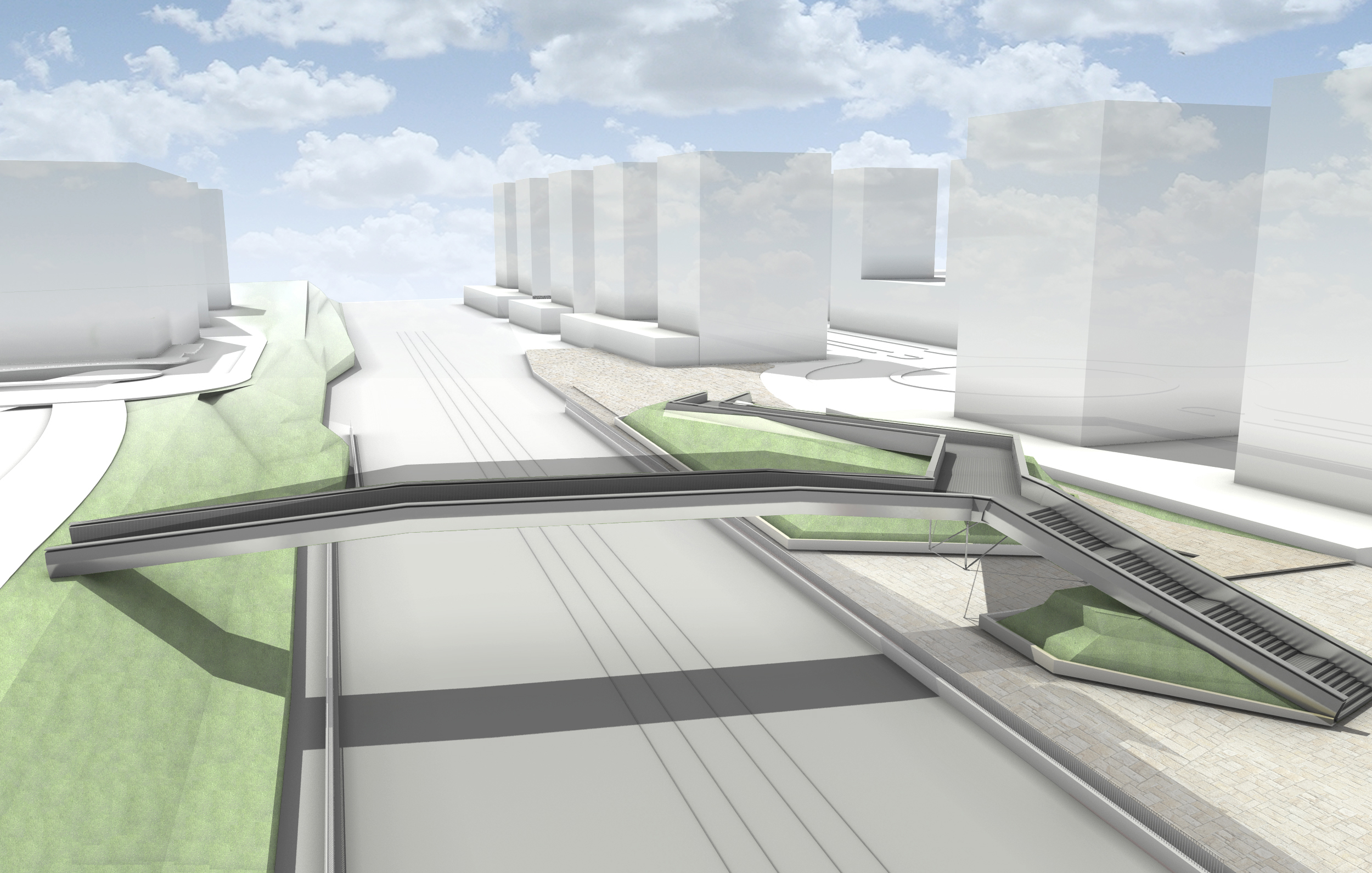
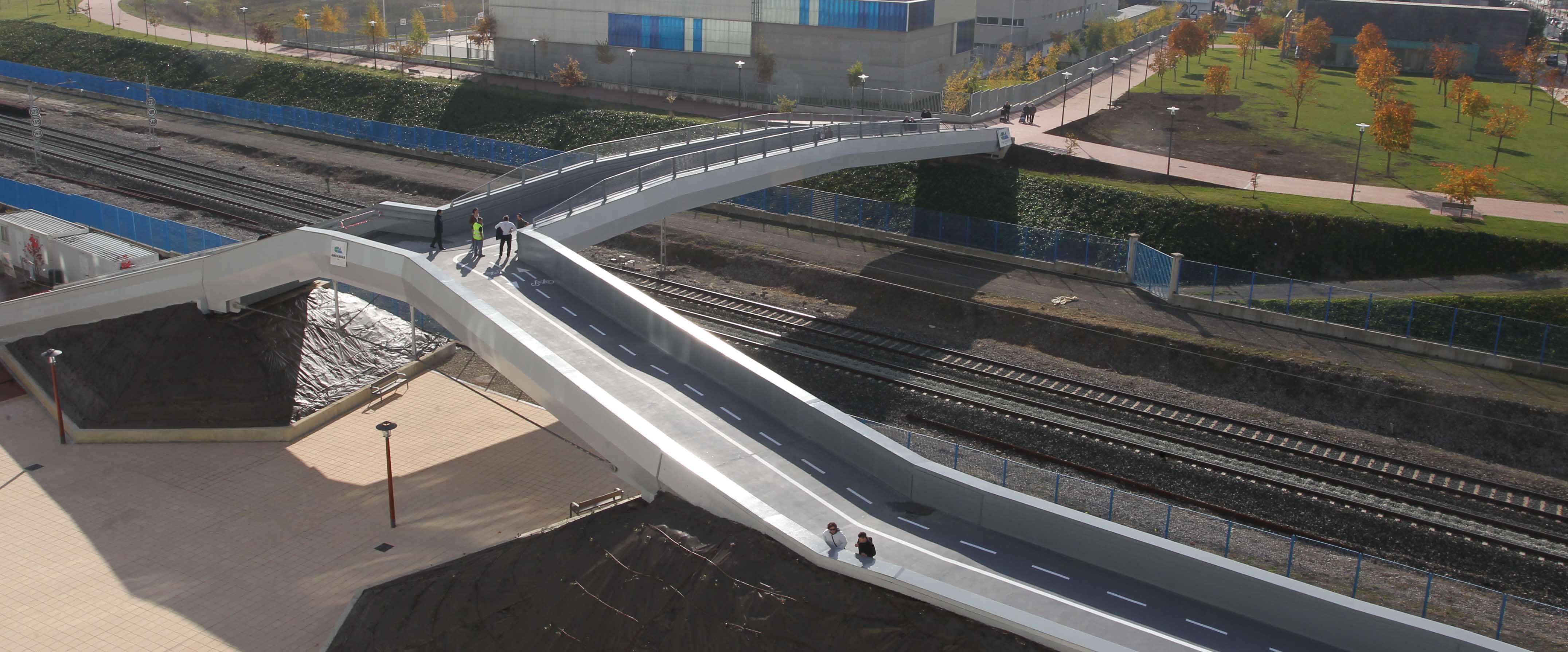
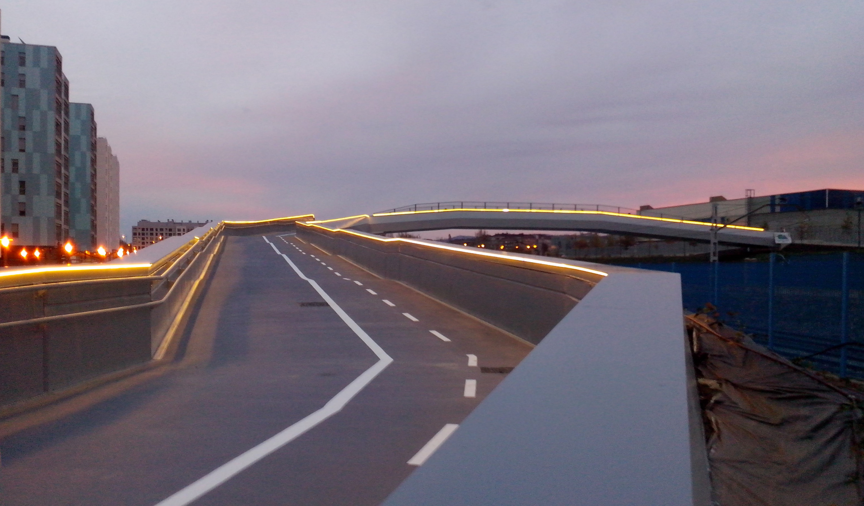
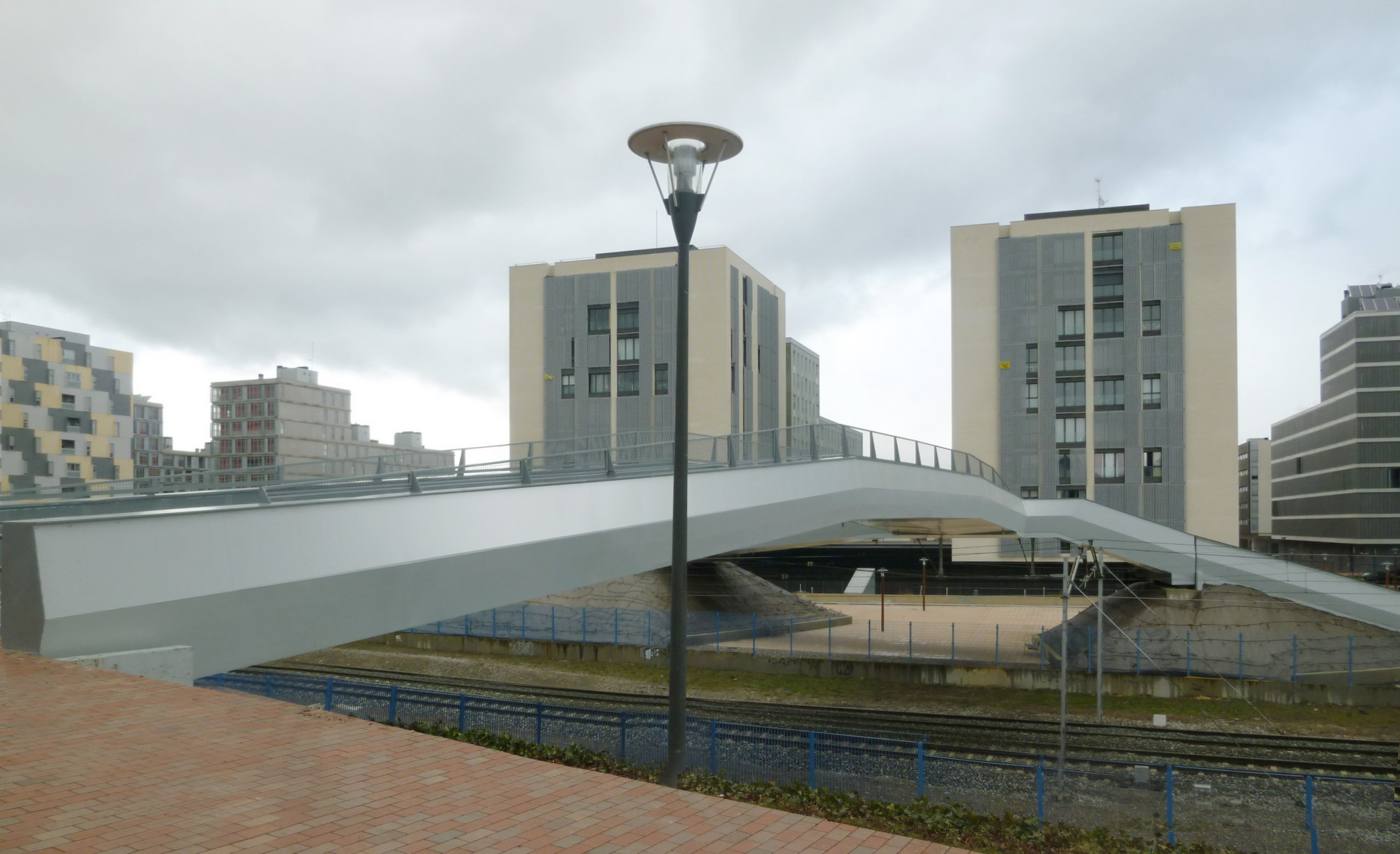
Necessary railway vertical and horizontal clearance together with accessibility requests have imposed that northern access are separated in a northeast stair and a northwestern ramp, mere than one hundred meters long.
B - New green area
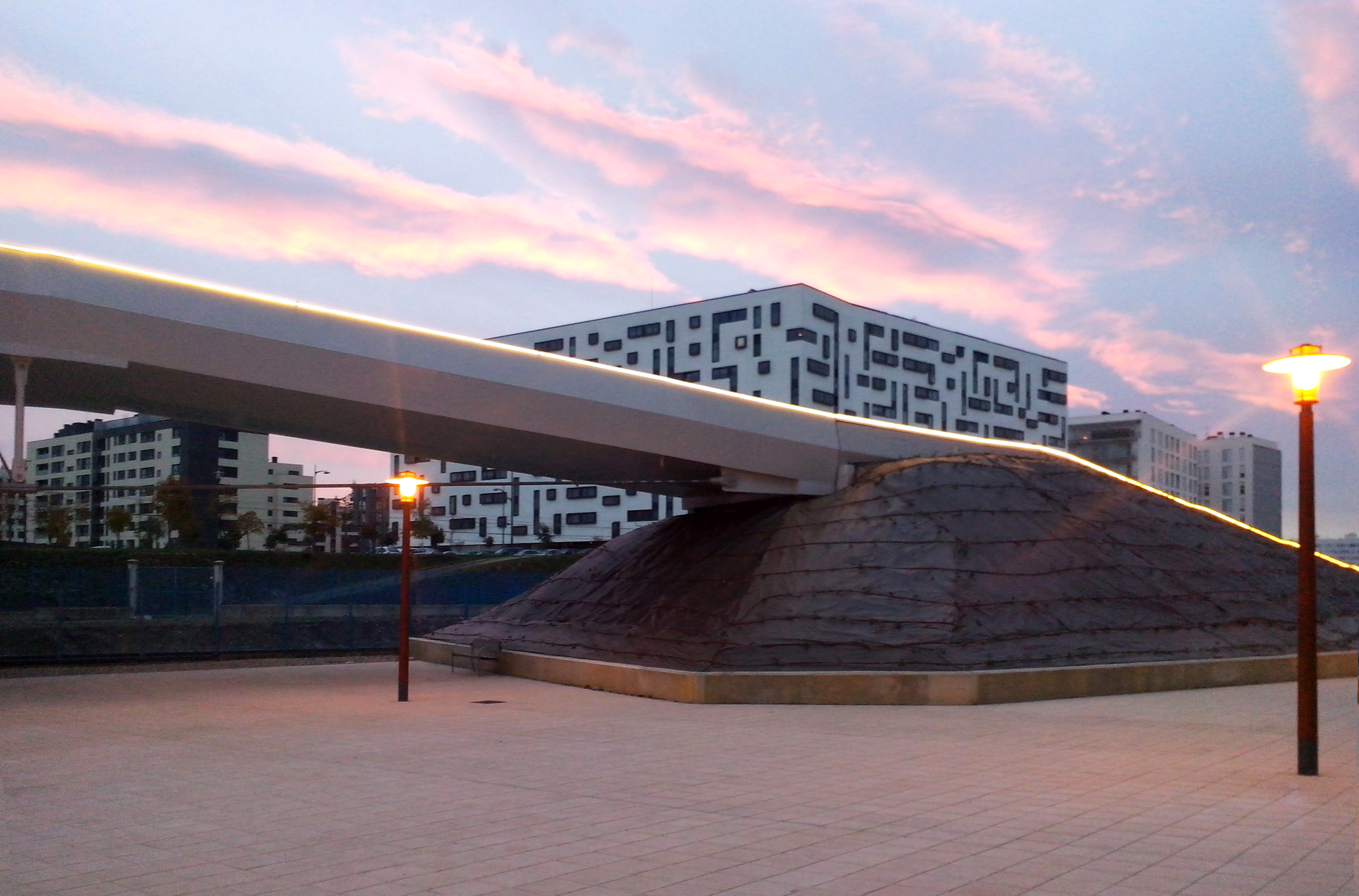
The northwestern ramp has been mainly constructed by an earth embankment, generating a new topography that in one hand protects and isolates the existing buildings from railway traffic and, in the other hand, created a new green area, as an extension of the large green zones of the area.
C - Formal minimalism and structural optimization
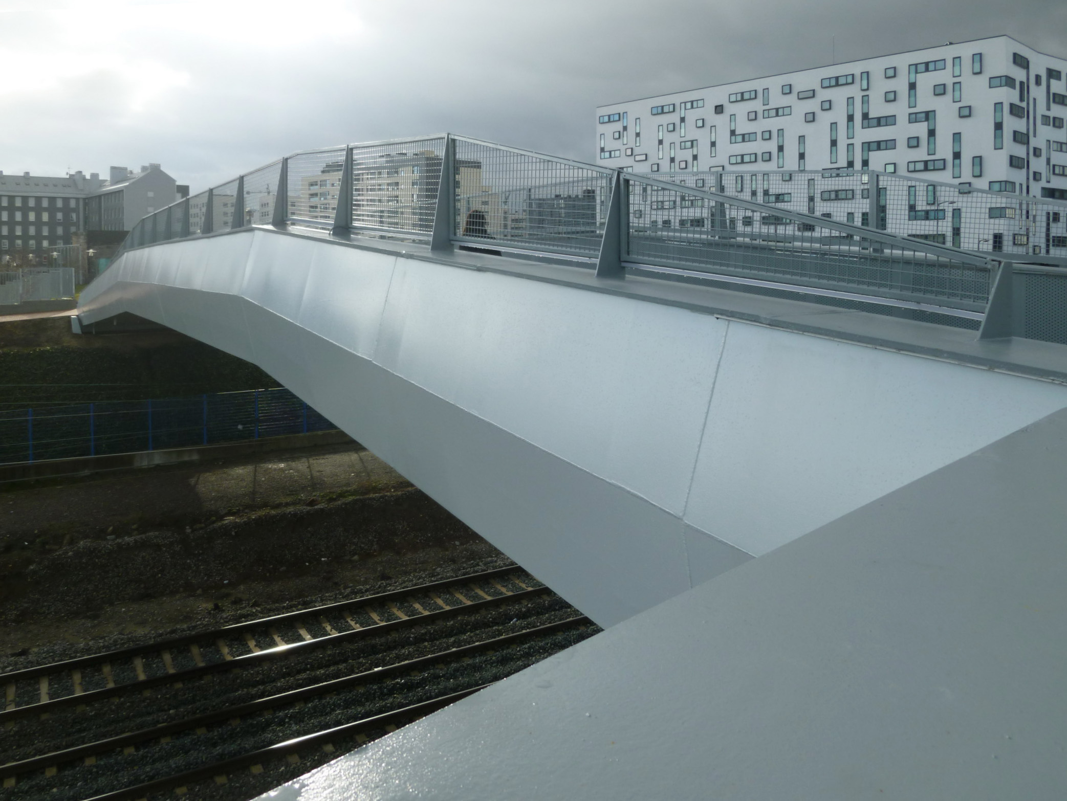
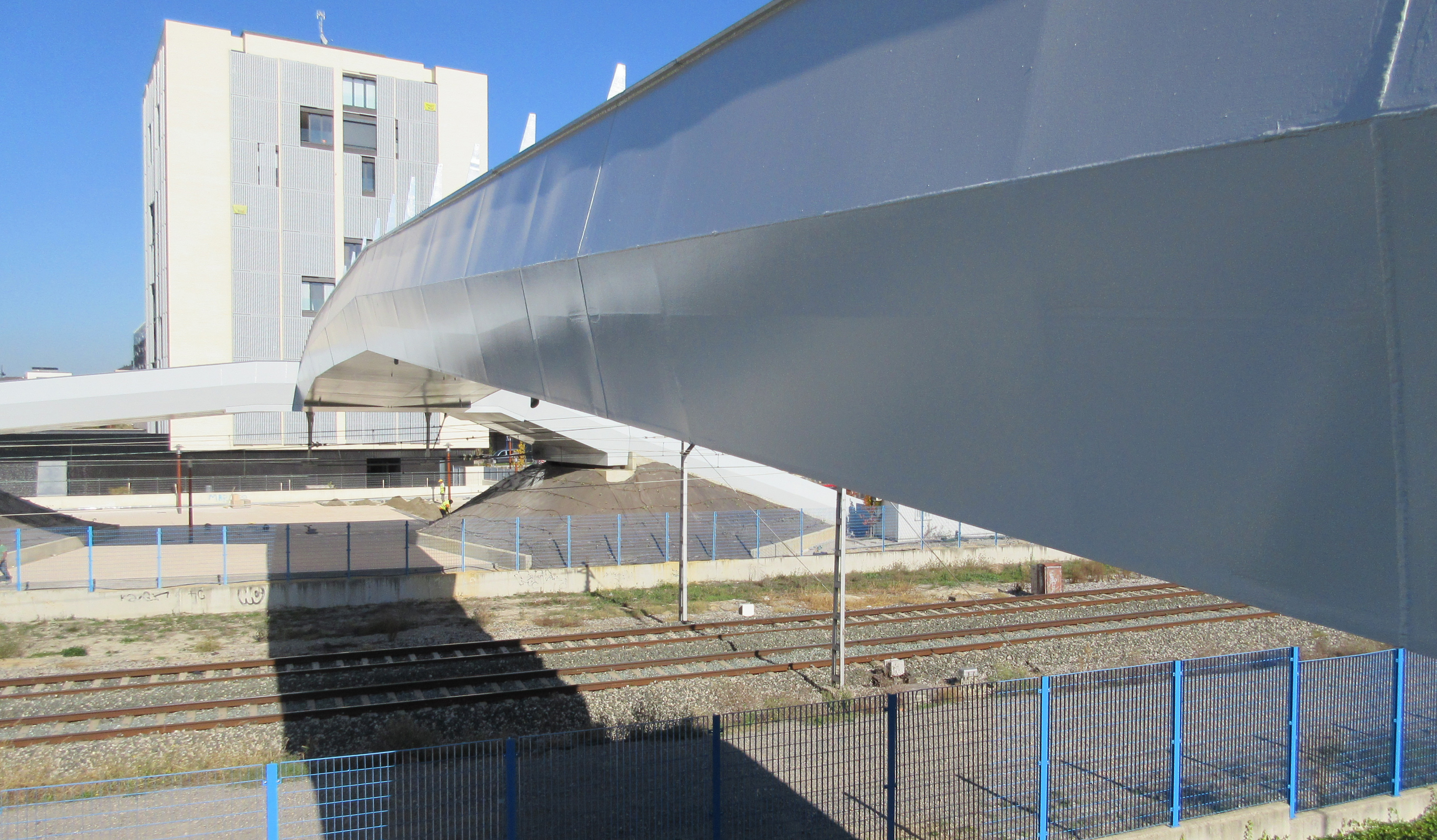
The footbridge design intended to minimize visual intrusion and therefore massive elements were discarded and the solution designed with a sole element that would not rival with the surrounding and existing elements.
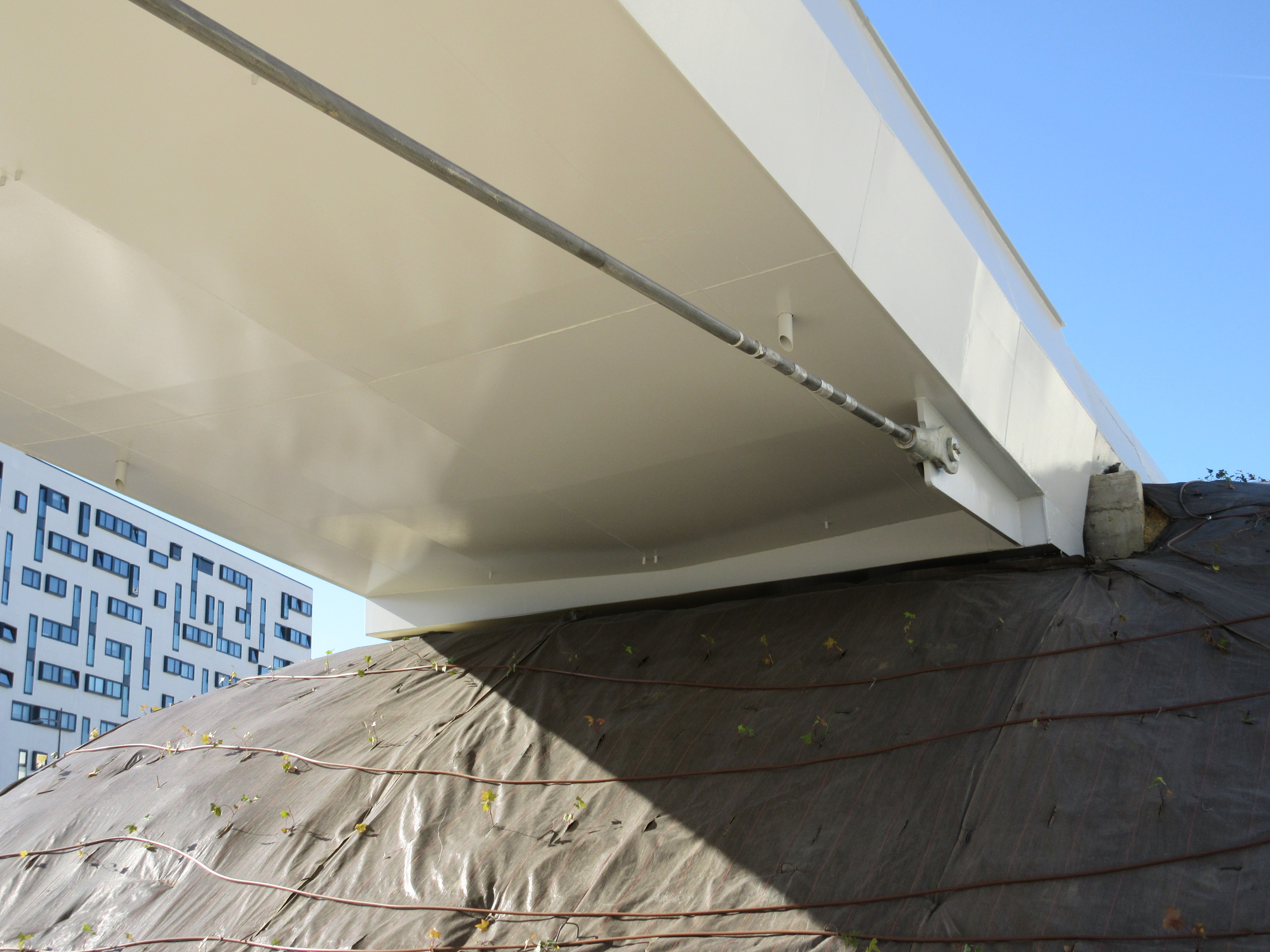
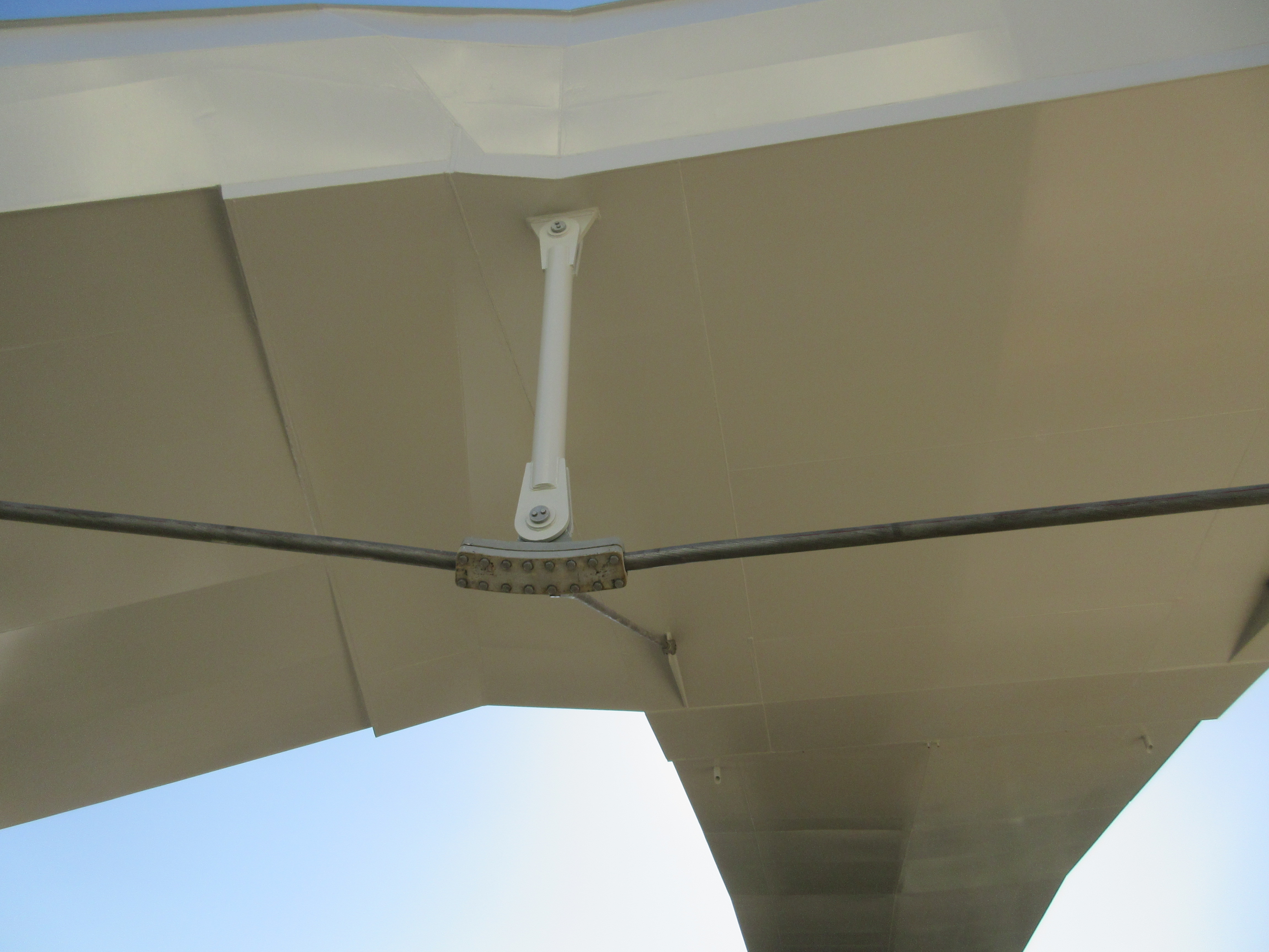
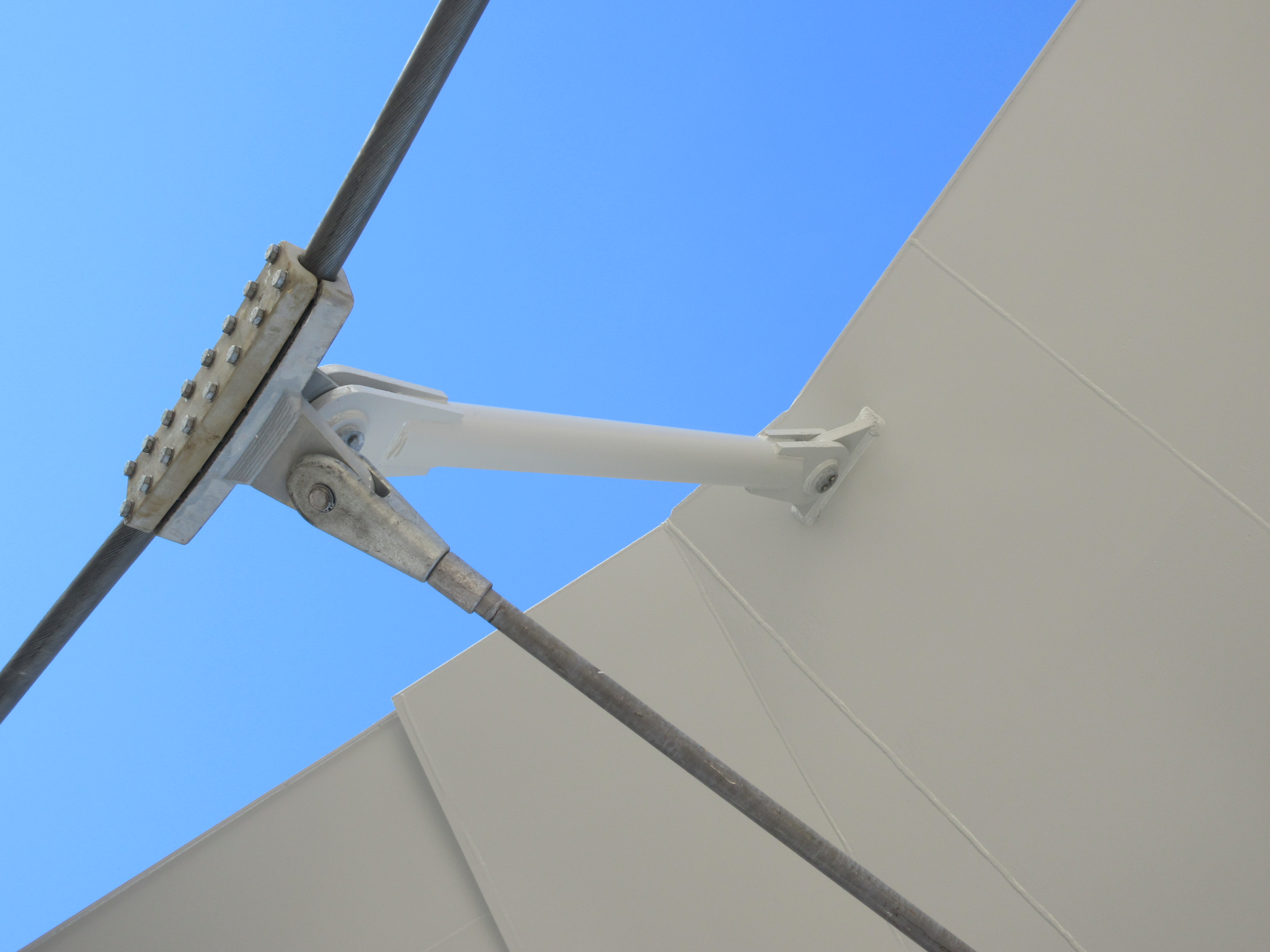
The footbridge deck has thus been designed with a simple geometry, consistent with the recent urban development in Zabalgana. The deck is a steel beam with a U shaped cross section and constant height, diverting in the northern ramp and stair with formal continuity.


