| HS Riudellots de la Selva Viaduct | |
| Ruidellots, Spain | |
| Structural typology | Railway Bridges |
| Date | September, 2009 |
| Scope | Detailed design and construction support |
| Cliente | Project: PROINTEC / Technical support: ACCIONA |
| Design | Fhecor |
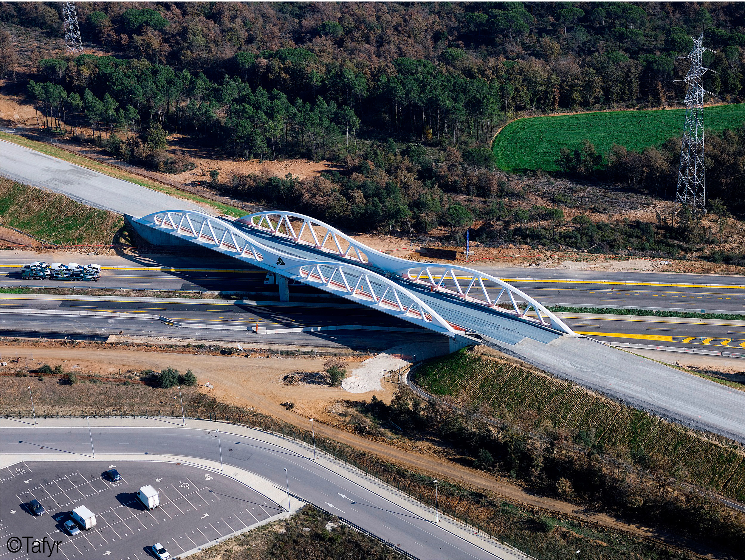
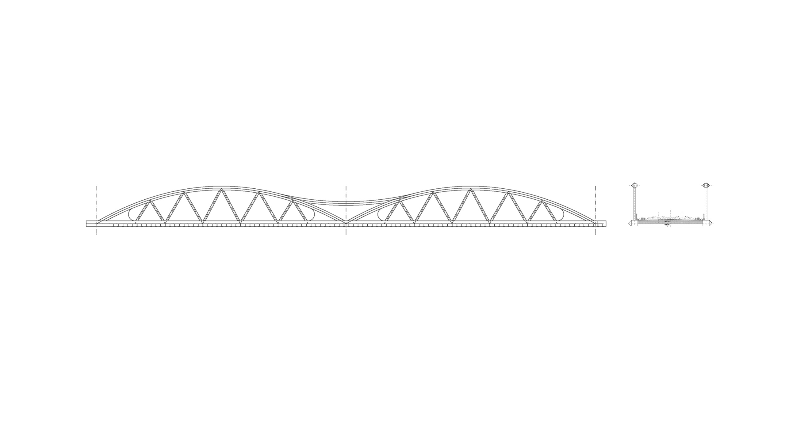
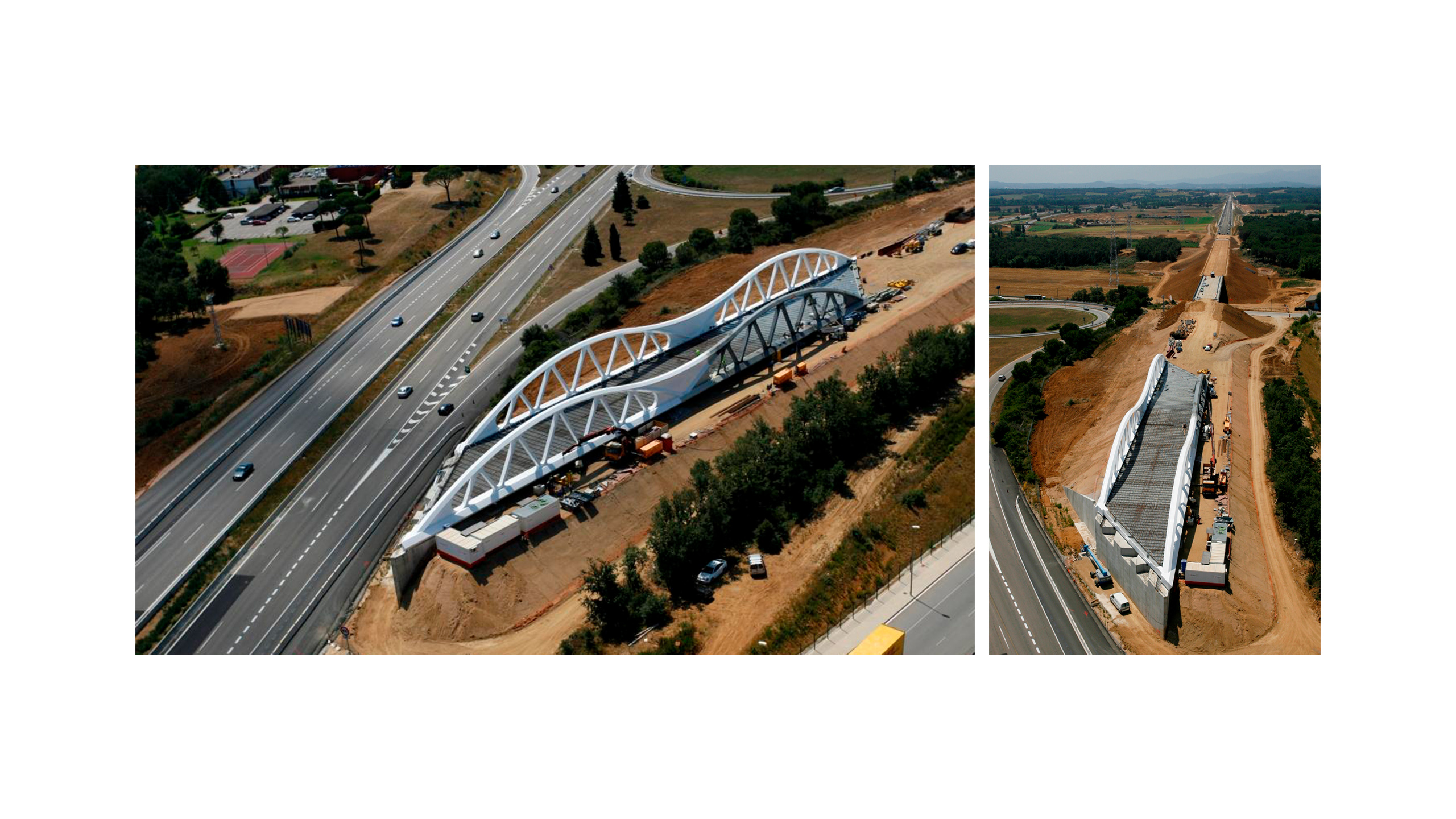
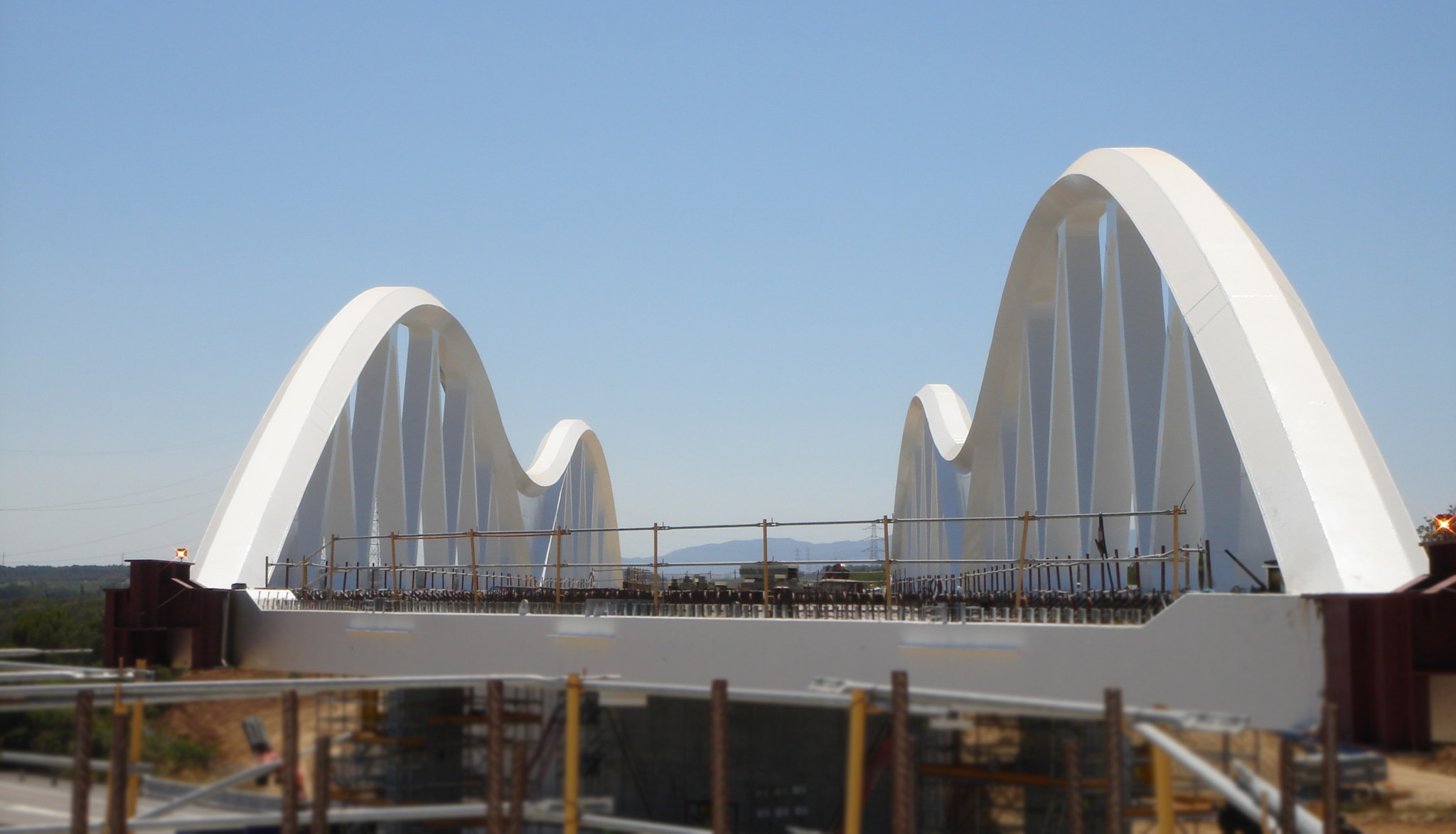
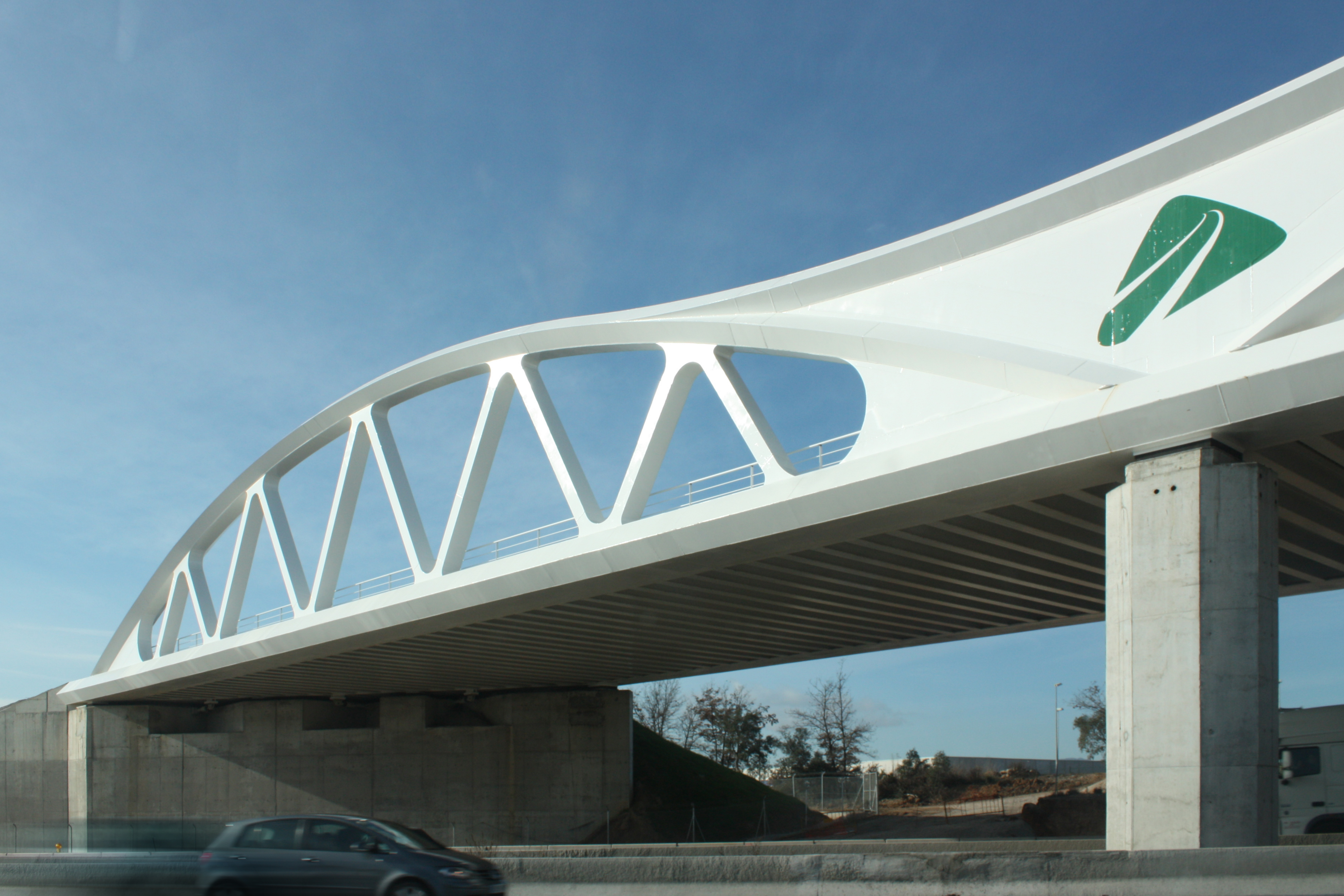
The structure consists of a single two span deck of 53.0m + 53.0m between axes giving a total length of 106.0m. The structure has a marked skew and therefore the axis supports on the piers and abutments offer an angle of 34.3° on the high speed train line. The width of the deck is a constant 15.70m.
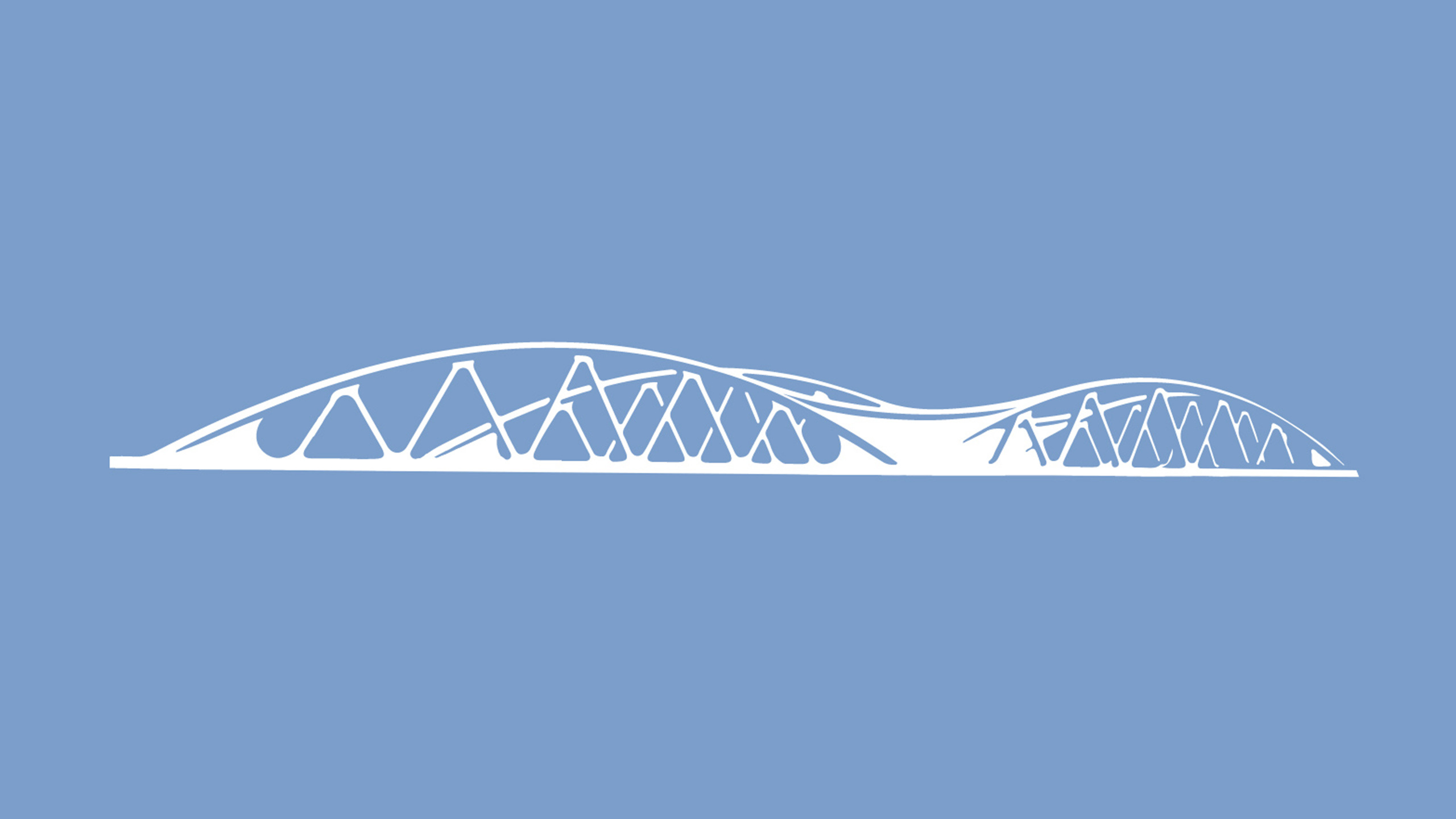
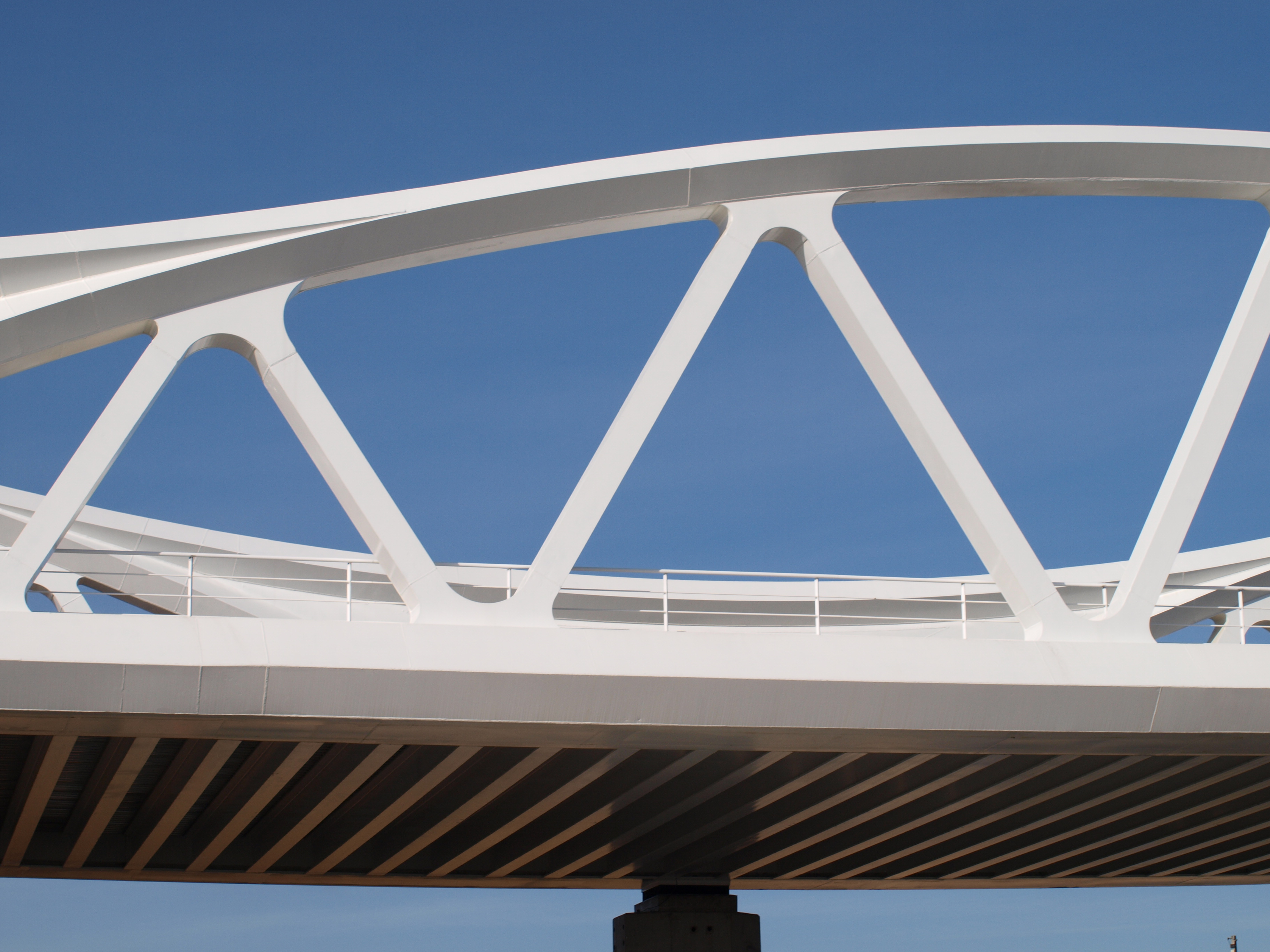
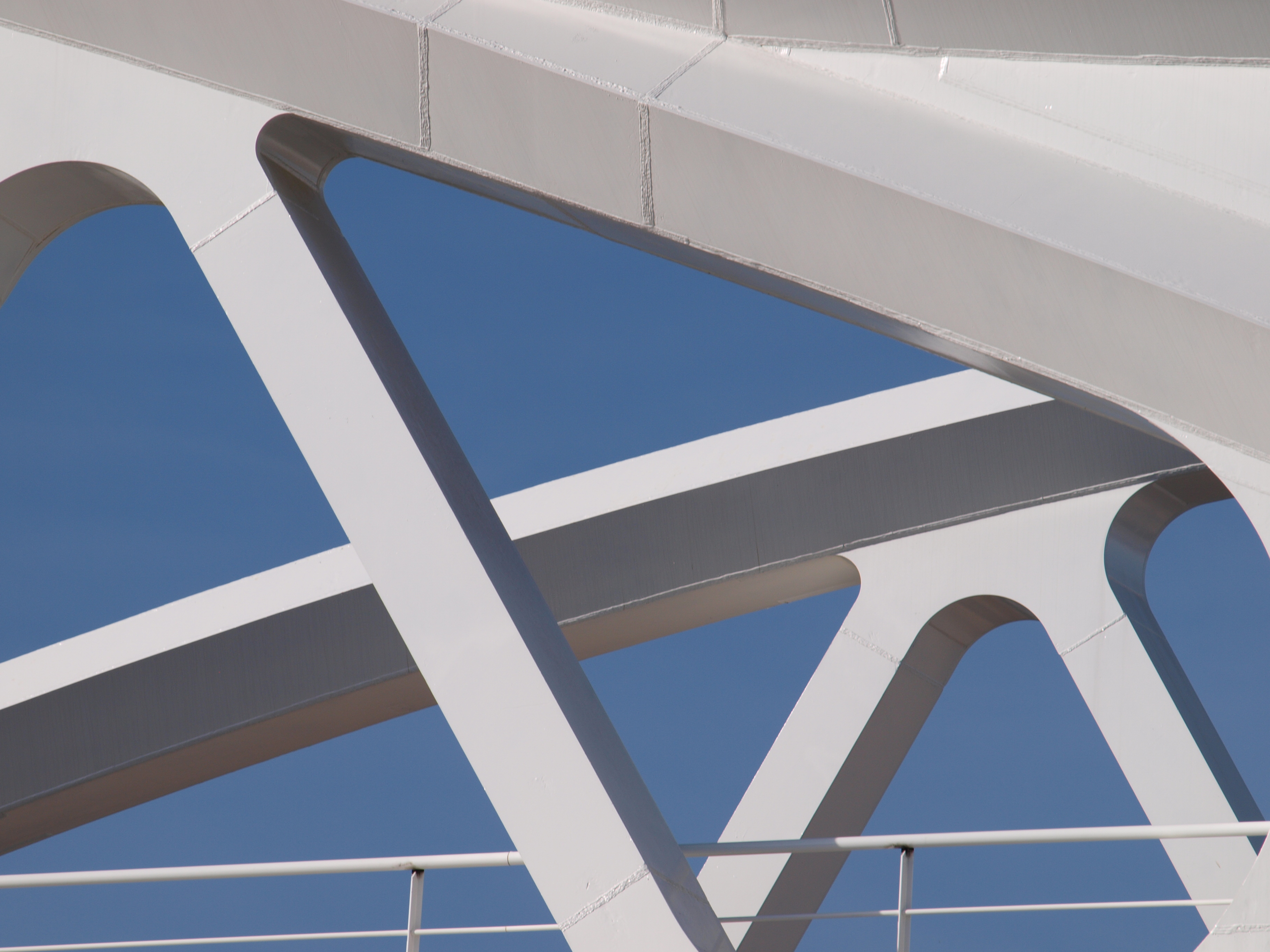
The structure consists of two longitudinal steel truss girders, with the upper chord parabolically arranged on the extremes of the transversal cross-section and separated at a distance of 14.40m between axes. The rise of the parabola at the centre of each span is 7.60m between the upper and lower chord axes. Continuity is given to the upper chords between one span and another employing a counter parabola over the pier supports which are placed 15.0m on each side of the piers and with a depth of 4.30m on supports between continuity and lower chords.
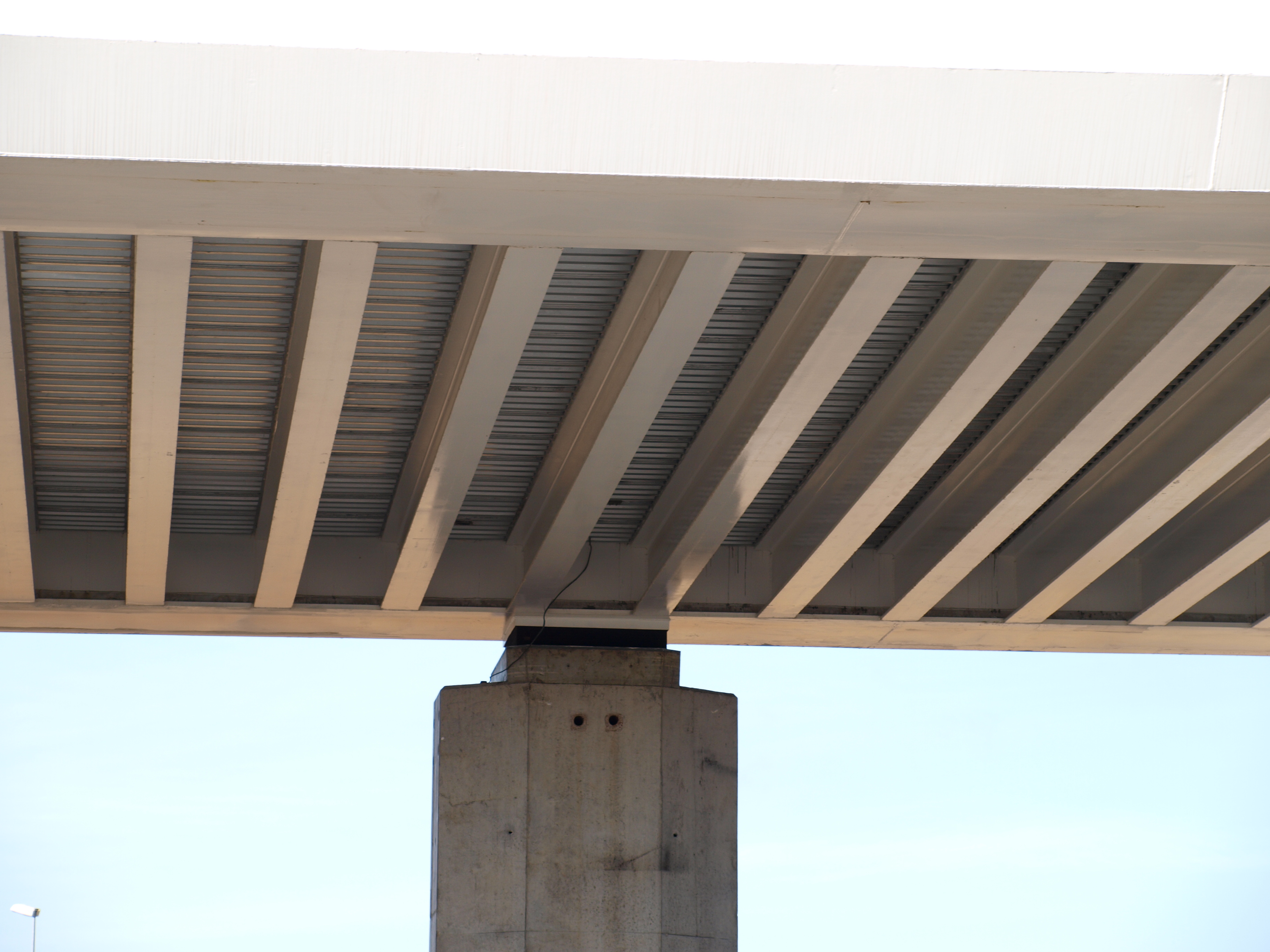
The deck between the longitudinal girders is formed by a hollow reinforced concrete slab between the lower chords of the truss girders which is placed on HEB-600 steel profiles set every 1.0m. The slab depth goes from 0.60m at the lower chords to 0.73 in the centre; hence the upper face of the slab has a 2% camber from its centre to the truss. The slab is cast over lost formwork composed of corrugated steel sheeting supported on HEB steel profiles.


