alpera_e3_fly_7790.jpg
HSL Madrid – Alicante. Alpera By-pass. Alpera Viaduct
Alicante, España
Typologie Railway Bridges
Date Avril, 2001
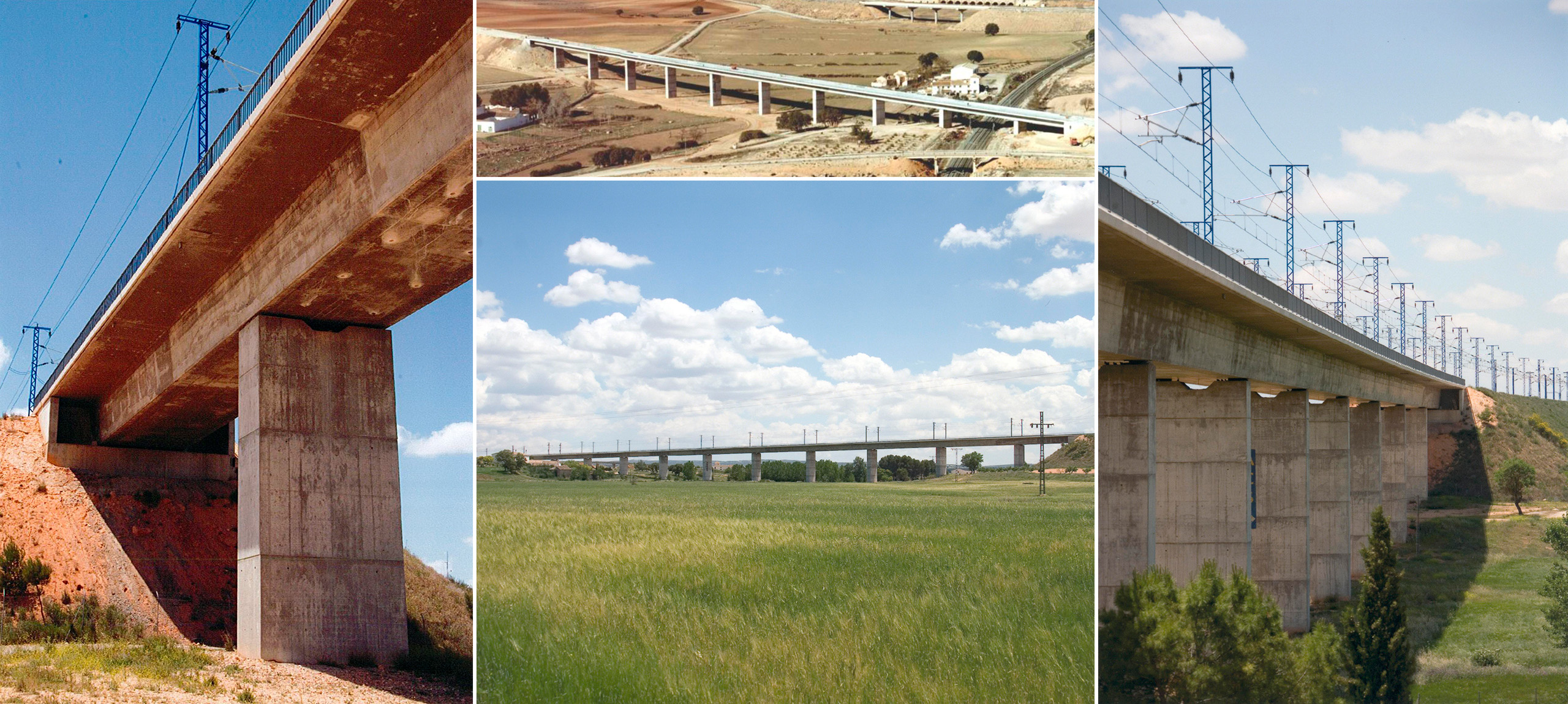
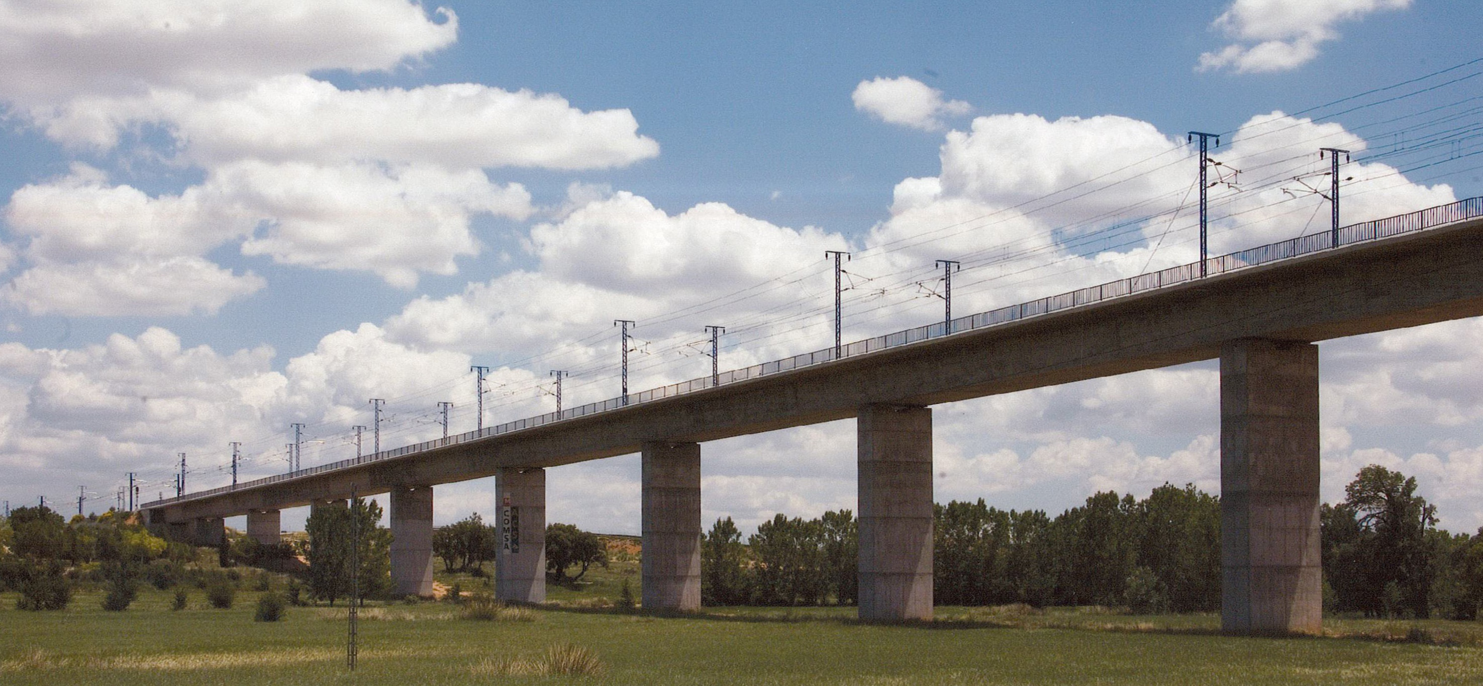
This structure consists of 11 spans of 30.00m + 9 x 45.00m + 30.00m. The bridge is 13.00m wide therefore permitting a two-way high-speed railway line.

It is a post-tensioned, continuous box-section beam. The depth of the deck is a constant 3.20m which is 1/14 of the main span.

The great height of abutment 2, approximately 17.0m, and the importance of horizontal actions induced by train breaking and seismic effects condition the chosen abutment typologies. From an economic and a structural behavioral point of view, it seems more adequate that these horizontal forces of breaking and seismic effects should only be transferred to the lower abutment 1. Hence the reason for choosing the closed abutment type for the lower one (E-1) and the open version for the upper one (E-2).

The open abutment 2 is composed of two battered shafts which are placed directly below the supports of the deck and founded directly into the ground. In order to avoid the transmission of large horizontal forces from

deck to abutment, support employ pot bearings was chosen which allow the deck to slide once the horizontal force exceeds the value of Teflon friction, that is, 5% of the vertical load.
Pro
Abutment 1 is closed with buttresses and directly founded to the ground via footings. The deck support is also achieved by means of pot bearings as for the transmission of horizontal forces devices are supplied which allow slow movements and are able to act as dampers against breaking impact (which permit the deck to stay fixed to the abutment) and as energy dissipaters regarding seismic effects.

The infrastructure is composed of 10 rectangular, hollow-section bevel-edged piers. The deck is supported on the piers and abutments via two neoprene bearings. On the two central piers, laminated bearings are placed so as to compensate deck movements and to re-center the bridge in place, both for breaking as for seismic actions. Moreover, it is possible to fix the point for rheological movements in the center of the bridge and to minimize them.
This structure consists of 11 spans of 30.00m + 9 x 45.00m + 30.00m. The bridge is 13.00m wide therefore permitting a two-way high-speed railway line.

It is a post-tensioned, continuous box-section beam. The depth of the deck is a constant 3.20m which is 1/14 of the main span.

The great height of abutment 2, approximately 17.0m, and the importance of horizontal actions induced by train breaking and seismic effects condition the chosen abutment typologies. From an economic and a structural behavioral point of view, it seems more adequate that these horizontal forces of breaking and seismic effects should only be transferred to the lower abutment 1. Hence the reason for choosing the closed abutment type for the lower one (E-1) and the open version for the upper one (E-2).

The open abutment 2 is composed of two battered shafts which are placed directly below the supports of the deck and founded directly into the ground. In order to avoid the transmission of large horizontal forces from

deck to abutment, support employ pot bearings was chosen which allow the deck to slide once the horizontal force exceeds the value of Teflon friction, that is, 5% of the vertical load.
Abutment 1 is closed with buttresses and directly founded to the ground via footings. The deck support is also achieved by means of pot bearings as for the transmission of horizontal forces devices are supplied which allow slow movements and are able to act as dampers against breaking impact (which permit the deck to stay fixed to the abutment) and as energy dissipaters regarding seismic effects.

The infrastructure is composed of 10 rectangular, hollow-section bevel-edged piers. The deck is supported on the piers and abutments via two neoprene bearings. On the two central piers, laminated bearings are placed so as to compensate deck movements and to re-center the bridge in place, both for breaking as for seismic actions. Moreover, it is possible to fix the point for rheological movements in the center of the bridge and to minimize them.
HSL Madrid – Alicante. Alpera By-pass. Alpera Viaduct
Alicante, España
Typologie Railway Bridges
Date Avril, 2001
Mission Detailed design and construction support
This structure consists of 11 spans of 30.00m + 9 x 45.00m + 30.00m. The bridge is 13.00m wide therefore permitting a two-way high-speed railway line.

It is a post-tensioned, continuous box-section beam. The depth of the deck is a constant 3.20m which is 1/14 of the main span.

The great height of abutment 2, approximately 17.0m, and the importance of horizontal actions induced by train breaking and seismic effects condition the chosen abutment typologies. From an economic and a structural behavioral point of view, it seems more adequate that these horizontal forces of breaking and seismic effects should only be transferred to the lower abutment 1. Hence the reason for choosing the closed abutment type for the lower one (E-1) and the open version for the upper one (E-2).

The open abutment 2 is composed of two battered shafts which are placed directly below the supports of the deck and founded directly into the ground. In order to avoid the transmission of large horizontal forces from

deck to abutment, support employ pot bearings was chosen which allow the deck to slide once the horizontal force exceeds the value of Teflon friction, that is, 5% of the vertical load.

Abutment 1 is closed with buttresses and directly founded to the ground via footings. The deck support is also achieved by means of pot bearings as for the transmission of horizontal forces devices are supplied which allow slow movements and are able to act as dampers against breaking impact (which permit the deck to stay fixed to the abutment) and as energy dissipaters regarding seismic effects.

The infrastructure is composed of 10 rectangular, hollow-section bevel-edged piers. The deck is supported on the piers and abutments via two neoprene bearings. On the two central piers, laminated bearings are placed so as to compensate deck movements and to re-center the bridge in place, both for breaking as for seismic actions. Moreover, it is possible to fix the point for rheological movements in the center of the bridge and to minimize them.
compo_alpera_7791.jpg
emplacement
Projets en lien